The right preparation can turn an interview into an opportunity to showcase your expertise. This guide to Machining (e.g., CNC, Milling, Turning) interview questions is your ultimate resource, providing key insights and tips to help you ace your responses and stand out as a top candidate.
Questions Asked in Machining (e.g., CNC, Milling, Turning) Interview
Q 1. Explain the difference between CNC milling and turning.
CNC milling and turning are both subtractive manufacturing processes using computer numerical control (CNC) machines, but they differ significantly in how they remove material. Think of it like this: milling is like carving with a chisel, while turning is like whittling with a knife.
CNC Milling: Uses rotating cutters to remove material from a workpiece that is typically stationary. The cutter moves in multiple axes (X, Y, and Z) to create complex shapes and features. Imagine sculpting a three-dimensional statue from a block of material. This is ideal for creating complex shapes with flat surfaces, holes, pockets, and grooves.
CNC Turning: Uses a rotating workpiece that is held in a chuck or collet. A cutting tool, typically a single-point tool, removes material by moving along the rotating workpiece’s axis (Z-axis and sometimes X). It’s like shaping a cylinder of wood on a lathe, creating shapes with rotational symmetry. This is best for creating cylindrical parts, shafts, and components with round profiles.
In short: Milling works on stationary workpieces with moving tools for various shapes, while turning works on rotating workpieces with moving tools for shapes with rotational symmetry.
Q 2. What are the common types of cutting tools used in CNC machining?
The types of cutting tools used in CNC machining vary greatly depending on the material being machined and the desired finish. Some common types include:
- End Mills: These have multiple cutting edges and are used for milling operations, creating various shapes like pockets, slots, and profiles. They come in many designs, like ball-nose, flat-end, and bull-nose.
- Drills: Used for creating holes. Different drill bit types exist, such as twist drills, step drills, and counterbores, each suited for specific hole types and applications.
- Taps and Dies: Taps are used to create internal threads, and dies create external threads. These are essential for creating threaded components and fasteners.
- Single-Point Turning Tools: These are used in turning operations, typically made of carbide or ceramic, offering strength and precision. These are shaped specifically for different operations like facing, grooving and turning.
- Reamers: These are used to enlarge and precisely size existing holes after drilling.
- Face Milling Cutters: These are designed for planar milling, achieving a smooth, flat surface.
The selection of the right cutting tool is crucial for achieving the desired surface finish and dimensional accuracy. Choosing a tool with inappropriate geometry or material can lead to poor results or even tool breakage.
Q 3. Describe the process of setting up a CNC machine for a specific job.
Setting up a CNC machine for a job is a meticulous process requiring precision and attention to detail. Here’s a step-by-step breakdown:
- Workpiece Securing: The workpiece must be securely clamped or fixtured to the machine table to prevent movement during machining. Incorrect clamping can lead to inaccurate parts or even machine damage.
- Tool Selection and Setup: Select the appropriate cutting tools based on the material and the machining operations. These are loaded into the machine’s tool magazine, and their lengths are carefully measured and set for accurate machining.
- Work Coordinate System (WCS) Definition: The WCS defines the origin point for the CNC program. Accurate WCS setup is crucial for proper part positioning.
- Program Loading and Verification: The CNC program (G-code) is loaded into the machine’s control unit. A simulation run is highly recommended to verify the program’s path and prevent collisions.
- Zero Point Offset (G54, G55, etc.): These codes are utilized to define additional reference points to account for differences in the workpiece’s actual position.
- Spindle Speed and Feed Rate Selection: This is crucial for obtaining quality surface finish and cutting effectiveness. It is dependent on material, cutting tool geometry, and desired finish.
- Test Cut (Optional): A small test cut is performed to ensure that the program works correctly, the setup is correct, and the tool is cutting appropriately.
- Final Run: If the test cut is successful, the full program can be executed.
Every step needs to be verified. Even a small mistake can result in wasted material, damaged tools, or even a machine crash.
Q 4. How do you determine the appropriate cutting parameters (speed, feed, depth of cut)?
Determining the right cutting parameters (speed, feed, and depth of cut) is critical for efficient and effective machining. Incorrect parameters can lead to poor surface finish, tool breakage, or even machine damage. The selection depends on several factors:
- Material: Different materials (steel, aluminum, titanium, etc.) have different machinability characteristics. Harder materials usually require lower speeds and feeds.
- Cutting Tool Material and Geometry: The tool’s material (carbide, high-speed steel, ceramic) and geometry affect its cutting performance. Sharper tools can generally handle higher feeds.
- Desired Surface Finish: A finer surface finish requires lower feeds and potentially higher speeds.
- Machine Capabilities: The machine’s power and rigidity influence the maximum achievable cutting parameters.
Approaches to Parameter Determination:
- Machinability Data Handbooks: These provide recommended cutting parameters for various material-tool combinations.
- Manufacturer Recommendations: Cutting tool manufacturers often provide recommendations for their tools.
- Trial and Error (with caution): Start with conservative parameters and gradually increase them while monitoring for tool wear and surface finish.
- CNC Software Features: Some CAM software includes toolpath optimization capabilities that can assist in parameter selection.
Remember, safety is paramount. Always start with conservative parameters and gradually increase them based on observations. Monitoring for vibration, excessive tool wear, and unusual sounds are crucial for successful machining.
Q 5. What are the different types of CNC machine control systems?
CNC machine control systems are the brains behind the operation. They interpret the G-code instructions and control the machine’s movements. Common types include:
- Open-loop systems: These systems do not have feedback mechanisms to monitor the actual position of the machine axes. They are less accurate but simpler and cheaper.
- Closed-loop systems (servo systems): These use feedback sensors (encoders or resolvers) to measure the actual position of the axes and compare it to the commanded position. Any discrepancy is corrected by the control system, leading to higher accuracy and repeatability. Most modern CNC machines use closed-loop systems.
Different manufacturers offer proprietary systems, but they all share common underlying principles: reading G-Code instructions, calculating motor movements, controlling axis speeds and feed rates, monitoring machine status (temperature, speed, and position), and providing user interface for programming and monitoring.
The sophistication of these systems impacts the capabilities of the machine. More advanced controllers support advanced features such as adaptive control, automatic tool change, and sophisticated diagnostics.
Q 6. Explain the concept of G-code programming.
G-code is the programming language used to control CNC machines. It’s a set of alphanumeric commands that specify the movements of the machine’s axes, spindle speed, coolant control, and other machine functions. Think of it as a recipe for the machine to follow, telling it exactly what to do and where to go.
Key elements of G-code:
- G-codes: Preparatory codes that specify the type of motion (e.g.,
G00for rapid traverse,G01for linear interpolation). - M-codes: Miscellaneous functions (e.g.,
M03to start the spindle,M30to end the program). - Coordinates (X, Y, Z): Specify the position of the tool in the machine’s coordinate system.
- Feed Rate (F): Specifies the speed at which the tool moves.
- Spindle Speed (S): Specifies the rotational speed of the spindle.
Example G-code snippet:
G90 G01 X10.0 Y20.0 F100 ; Move to X10, Y20 at 100 mm/minG01 Z-5.0 F50 ; Move to Z-5 at 50 mm/min (start cutting)G01 X20.0 Y30.0 F100 ; Cut along the line to X20, Y30M30 ; End of programG-code is generated using Computer Aided Manufacturing (CAM) software that translates a 3D CAD model into a set of instructions for the CNC machine. Understanding G-code is essential for CNC programmers and machinists.
Q 7. How do you troubleshoot common CNC machine errors?
Troubleshooting CNC machine errors requires a systematic approach. It often involves checking various aspects of the system:
- Error Messages: Examine the machine’s control panel for any error messages. These often provide clues to the source of the problem.
- Program Review: Check the G-code program for any syntax errors, incorrect coordinates, or illogical commands. Simulation software can be very useful here.
- Tooling and Workholding: Inspect the cutting tools for wear or damage, and ensure that the workpiece is properly secured. A loose workpiece is a common source of errors.
- Machine Components: Check the machine’s mechanical components, such as the slides, bearings, and spindle, for any signs of wear or malfunction. Listen for unusual sounds during operation.
- Coolant System: Ensure that the coolant system is functioning correctly. Insufficient coolant can lead to overheating and tool wear.
- Electrical Connections: Inspect all electrical connections for looseness or damage.
- Sensor Readings: Examine the machine’s sensor readings (e.g., temperature, pressure) for any anomalies.
Systematic Troubleshooting: A structured troubleshooting methodology, such as a flowchart or decision tree, can improve the effectiveness of error identification and resolution.
Safety First: Always ensure that the machine is powered down and locked out before attempting any repairs or maintenance. Consult the machine’s manuals and documentation whenever necessary.
Q 8. Describe your experience with various machining materials (e.g., steel, aluminum, plastics).
My experience spans a wide range of machining materials, each presenting unique challenges and requiring specific machining parameters. Steel, for instance, is known for its strength and durability but can be difficult to machine due to its hardness. I’ve worked extensively with various grades of steel, from mild steel requiring relatively low cutting speeds to high-strength alloys demanding specialized tooling and cutting fluids to prevent tool wear and heat build-up. Aluminum, on the other hand, is much softer and easier to machine, allowing for higher cutting speeds and feeds. However, its tendency to work-harden requires careful consideration of cutting parameters to prevent surface damage. I’ve machined aluminum alloys for aerospace applications, where precision and surface finish are critical. Finally, plastics offer a completely different set of considerations. The variety of plastics, from soft thermoplastics to high-performance engineering plastics, necessitates a different approach to machining. I’ve worked with polymers requiring specialized tooling to avoid chipping and melting, focusing on precise control of cutting speeds and depth of cut to maintain dimensional accuracy.
For example, when machining a complex steel component for a heavy-duty application, I’d use a carbide cutting tool with appropriate geometry and select cutting parameters based on the specific grade of steel and desired surface finish. With aluminum, a high-speed steel (HSS) tool might suffice, and higher cutting speeds would be feasible. For plastics, I might use diamond or ceramic tools to minimize heat generation and ensure a clean cut, often using lower speeds and feeds to avoid melting or deformation. The choice of cutting fluid also varies considerably depending on the material; some materials benefit from flood coolant to dissipate heat, while others may require minimal lubrication to avoid unwanted reactions.
Q 9. What safety precautions do you follow while operating CNC machinery?
Safety is paramount in CNC machining. Before even touching the machine, I always perform a thorough pre-operational check, verifying the tool setup, workpiece clamping, and the overall machine’s condition. I make sure all safety guards are in place and functioning correctly. This includes ensuring the coolant system is operating effectively and properly shielded to prevent splashing. I always wear appropriate personal protective equipment (PPE), including safety glasses, hearing protection, and ideally, a face shield. Loose clothing and jewelry are strictly prohibited to avoid entanglement. During operation, I maintain a safe distance from the moving parts of the machine and monitor the process closely for any unusual vibrations, noises, or tool breakage. In the event of a malfunction, I immediately shut down the machine and assess the situation before attempting any repairs. Regular machine maintenance is critical to preventing accidents, so I follow a strict schedule of inspections and lubrication. Finally, I adhere strictly to the company’s safety protocols and always report any near misses or incidents to my supervisor.
Think of it like driving a car – regular checks, adherence to rules, and careful monitoring are crucial for preventing accidents.
Q 10. How do you ensure the accuracy and precision of machined parts?
Ensuring accuracy and precision requires a multi-faceted approach. It starts with the design stage, where accurate CAD models and tolerance specifications are essential. Next, I carefully plan the machining process, selecting appropriate tooling, and optimizing the cutting parameters (speeds, feeds, and depths of cut) for the chosen material. Precise workholding is vital to prevent workpiece movement during machining. I use appropriate fixtures and clamps to securely hold the workpiece. Regular tool wear monitoring and compensation is also critical, as dull tools can lead to inaccuracies. I often use on-machine probing to verify the workpiece’s position and dimensions throughout the process. Regular calibration of the machine and its components, such as the spindle and linear axes, is essential. Finally, I use post-processing techniques such as inspection with CMM (Coordinate Measuring Machine) or other quality control instruments to verify the final product’s accuracy and conformance to specifications. For example, in aerospace machining, where tolerances are extremely tight (often in micrometers), all these steps become critically important.
Q 11. Explain the importance of tool wear monitoring and compensation.
Tool wear monitoring and compensation are crucial for maintaining accuracy and efficiency in machining. As cutting tools wear, their geometry changes, leading to reduced cutting performance, poor surface finish, and inaccurate dimensions. Monitoring tool wear can be done using various methods, including visual inspection, force monitoring, and vibration analysis. Visual inspection involves observing the tool for signs of wear such as chipping, cracking, or flank wear. Force monitoring measures the cutting forces, and changes in these forces can indicate tool wear. Vibration analysis detects changes in the machine’s vibration patterns which may indicate tool wear. When significant tool wear is detected, compensation is necessary. This can involve adjusting cutting parameters or using tool offsetting to maintain desired tolerances. The compensation method depends on the specific machine and controller being used. Some CNC machines allow for automated tool length and radius compensation based on the measured tool wear. Neglecting tool wear can lead to scrap parts, machine downtime, and even potential safety hazards.
Imagine a chef using a dull knife – it won’t cut efficiently, and the result will be messy. Similarly, worn tools in machining compromise accuracy and can cause damage.
Q 12. What are the different types of milling cutters and their applications?
Milling cutters come in various types, each designed for specific applications. Some common types include:
- End Mills: These are cylindrical cutters with cutting edges on their ends and sides, used for various operations like face milling, slot milling, and pocketing.
- Ball Nose End Mills: These have a spherical end, ideal for creating contoured surfaces and 3D shapes.
- Face Mills: Designed for facing operations, these have multiple cutting edges arranged around a circular periphery.
- Slot Drills: Used for cutting narrow slots or grooves.
- Shell Mills: Large diameter cutters used for heavy-duty face milling.
- Dovetail Cutters: Specialized cutters for creating dovetail joints.
The choice of cutter depends on factors such as the workpiece material, the desired surface finish, and the complexity of the machining operation. For example, a ball nose end mill is ideal for creating a smooth, curved surface, while a face mill is more suitable for roughing operations where speed is prioritized.
Q 13. Describe different types of lathe operations (e.g., facing, turning, boring).
Lathe operations involve removing material from a rotating workpiece using various cutting tools. Some common lathe operations include:
- Facing: Creating a flat, perpendicular surface on the end of a workpiece.
- Turning: Reducing the diameter of a cylindrical workpiece.
- Boring: Enlarging an existing hole in a workpiece.
- Drilling: Creating holes in a workpiece.
- Threading: Creating screw threads on the workpiece.
- Parting-off: Separating a section of the workpiece from the main body.
Each operation uses specialized cutting tools and techniques. For example, facing requires a tool positioned perpendicular to the workpiece’s axis, while turning uses tools that move parallel to the axis. Boring requires precision as the operation creates an internal diameter. Selecting the correct tooling and cutting parameters is crucial for achieving precise dimensions and surface finish.
Q 14. What is the significance of workholding in machining?
Workholding is critical in machining because it ensures the workpiece remains securely in place during the operation. Improper workholding can lead to inaccurate machining, damaged parts, and potential safety hazards. Various workholding methods exist, including:
- Chucks: Used for holding cylindrical workpieces, often found on lathes.
- Vices: Used for holding smaller, irregular workpieces, often found on milling machines.
- Fixtures: Custom-designed devices for holding workpieces in precise positions.
- Clamps: Used in conjunction with fixtures or other workholding methods.
The choice of workholding method depends on the workpiece’s shape, size, material, and the type of machining operation being performed. Proper workholding minimizes vibrations, workpiece deflection, and ensures consistent positioning for accurate machining results. Think of it like holding a piece of wood steady while sawing – you wouldn’t expect a precise cut if you were holding it loosely.
Q 15. Explain your experience with CAD/CAM software.
My experience with CAD/CAM software is extensive, encompassing both 2D and 3D design and manufacturing processes. I’m proficient in several industry-standard packages, including Mastercam, Fusion 360, and SolidWorks CAM. My expertise goes beyond simply using the software; I understand the underlying principles of toolpath generation, cutting strategies, and the optimization of machining parameters. For instance, in a recent project involving the creation of a complex impeller, I used Mastercam to generate efficient toolpaths minimizing material waste and maximizing surface finish. I leveraged the software’s simulation capabilities to preview the machining process and identify potential collisions or issues before running the actual program on the CNC machine, preventing costly errors. Beyond this, I’m comfortable working with various file formats such as DXF, STEP, and IGES, ensuring seamless integration with different design and manufacturing systems.
I also actively seek to stay current with the latest software updates and features. For example, recently I explored the advanced features in Fusion 360 related to additive manufacturing, allowing me to better integrate subtractive and additive processes for complex components.
Career Expert Tips:
- Ace those interviews! Prepare effectively by reviewing the Top 50 Most Common Interview Questions on ResumeGemini.
- Navigate your job search with confidence! Explore a wide range of Career Tips on ResumeGemini. Learn about common challenges and recommendations to overcome them.
- Craft the perfect resume! Master the Art of Resume Writing with ResumeGemini’s guide. Showcase your unique qualifications and achievements effectively.
- Don’t miss out on holiday savings! Build your dream resume with ResumeGemini’s ATS optimized templates.
Q 16. How do you interpret engineering drawings and specifications?
Interpreting engineering drawings and specifications is fundamental to my work. I begin by thoroughly reviewing the drawing, paying close attention to dimensions, tolerances, surface finishes, and material specifications. This includes identifying key features like datum references and geometric dimensioning and tolerancing (GD&T) symbols which are crucial for ensuring the part meets the required quality standards. I then cross-reference the drawing with the associated specifications, ensuring a clear understanding of the functional requirements and any specific manufacturing instructions. For example, a drawing might specify a specific surface roughness (Ra value) which I would then translate into appropriate machining parameters such as feed rate and cutting tool selection.
If there are ambiguities or unclear aspects, I proactively communicate with the design engineers to clarify these points before proceeding with the machining process. This proactive approach prevents errors and ensures the final product aligns precisely with the design intent. I’m comfortable interpreting a wide range of drawings including those using ISO and ANSI standards.
Q 17. Describe your experience with different types of measuring instruments (e.g., calipers, micrometers).
I possess extensive experience utilizing various measuring instruments, including calipers, micrometers, dial indicators, height gauges, and CMMs (Coordinate Measuring Machines). My proficiency extends beyond simply taking measurements; I understand the principles of precision measurement, including the identification and compensation for measurement errors, and the selection of the appropriate instrument for the required accuracy. For example, I would use a micrometer for highly precise measurements to within a few micrometers, while calipers might be sufficient for less demanding tolerances. I also frequently use dial indicators for checking runout and alignment during setup, ensuring the accuracy of the machining process itself.
My experience with CMMs allows me to perform complex 3D measurements, verifying the overall geometry and dimensional accuracy of complex parts. In one instance, using a CMM, I identified a minor deviation in a critical dimension on a precision component that would have otherwise gone undetected, preventing a potential failure in the final product.
Q 18. How do you handle complex or unusual machining tasks?
When confronted with complex or unusual machining tasks, I follow a systematic approach. First, I thoroughly analyze the task, breaking it down into smaller, more manageable steps. I then consult relevant resources, including technical manuals, industry best practices, and online communities if necessary, to research potential solutions. Simulation, using CAD/CAM software, becomes even more critical in these scenarios, allowing me to predict and mitigate potential challenges before they arise.
For example, I once faced a task involving the machining of a highly intricate component with numerous undercuts and complex internal features. I tackled it by creating a sequence of setups, using different tooling and techniques for each stage, ensuring minimal risk of damage and efficient material removal. My approach involved using multiple fixtures to securely hold the workpiece in varying orientations. This methodology, involving careful planning and simulation, led to the successful completion of the project, showcasing my adaptability and problem-solving skills.
Q 19. Explain your approach to problem-solving in a machining environment.
My approach to problem-solving in a machining environment is rooted in a systematic, data-driven methodology. I begin by precisely defining the problem, gathering relevant data through observation and measurement. I then analyze the data, identifying potential root causes. I generate several potential solutions, evaluating their feasibility and potential consequences before selecting the most effective and efficient solution. Finally, I implement the chosen solution and monitor its effectiveness, making adjustments as needed.
For instance, if a part exhibits inconsistent surface finish, I’d systematically investigate factors such as tool wear, improper feed rate, coolant application, and workpiece clamping. I might conduct controlled experiments, systematically altering one parameter at a time to pinpoint the cause of the problem. Through this method, I’ve successfully resolved issues ranging from tool breakage to dimensional inaccuracies, improving efficiency and minimizing waste.
Q 20. Describe your experience with quality control procedures in machining.
My experience with quality control procedures encompasses all stages of the machining process, from initial workpiece inspection to final product verification. I meticulously follow established procedures and utilize various quality control tools and techniques. This includes regularly checking for dimensional accuracy, surface finish, and overall part geometry using measuring instruments and CMMs, as previously described. I also maintain detailed records of all machining parameters and inspection results to ensure traceability and facilitate continuous improvement.
Implementing Statistical Process Control (SPC) techniques, like control charts, helps monitor process variation and identify potential problems early, allowing for timely corrective actions. Furthermore, I am well-versed in industry standards and specifications relevant to quality control in machining, adhering to relevant ISO standards. A commitment to quality control has resulted in consistently meeting or exceeding customer expectations throughout my career.
Q 21. What are your strengths and weaknesses as a machinist?
My greatest strengths lie in my meticulous attention to detail, my problem-solving abilities, and my commitment to continuous learning. I am a highly reliable and efficient worker, consistently delivering high-quality results. I also thrive in challenging environments and am always eager to tackle complex machining tasks. My ability to quickly learn and adapt to new technologies and techniques is crucial in this constantly evolving field.
One area for improvement I am actively addressing is delegating tasks more effectively. While I take pride in my ability to handle complex operations independently, recognizing when to delegate responsibilities and empowering team members would optimize overall workflow and allow for a more efficient division of labor. I am currently participating in a leadership training program to further refine this skill.
Q 22. How do you stay up-to-date with the latest machining technologies?
Staying current in the dynamic field of machining requires a multi-pronged approach. It’s not enough to rely solely on past experience; continuous learning is crucial.
Industry Publications and Journals: I regularly read publications like Modern Machine Shop, Manufacturing Engineering, and others focused on CNC machining, milling, and turning. These journals often feature articles on cutting-edge technologies, best practices, and emerging trends.
Trade Shows and Conferences: Attending industry events like IMTS (International Manufacturing Technology Show) allows me to see new equipment in action, network with peers, and learn about the latest advancements firsthand. I actively participate in workshops and seminars offered at these events.
Online Resources and Webinars: I utilize online platforms and professional organizations (like SME) that offer webinars, tutorials, and online courses focusing on specific machining techniques or software updates. This is a convenient way to stay informed on a regular basis.
Manufacturer Websites and Documentation: Keeping up with updates from major CNC machine manufacturers (e.g., Haas, Fanuc, Siemens) is crucial. Their websites often provide details on software updates, new machine features, and best practices for their equipment.
Networking with Peers: Engaging in discussions with other machinists, whether online or in person, exposes me to diverse perspectives and practical experiences. Sharing challenges and solutions helps everyone stay sharp and informed.
This combination of methods ensures I’m constantly learning and adapting to the ever-evolving landscape of machining technologies.
Q 23. Describe your experience with different types of coolants and lubricants.
My experience with coolants and lubricants is extensive, encompassing various types for different applications. The selection depends heavily on the material being machined, the machining process (milling, turning, etc.), and the desired surface finish.
Water-Soluble Coolants: These are widely used because they are relatively inexpensive, readily available, and effective at cooling and lubricating the cutting zone. However, they can contribute to rust if not properly managed. I’m experienced in maintaining proper coolant concentrations and regularly cleaning the machine’s coolant system to prevent bacterial growth and maintain efficiency.
Oil-Based Coolants: Used for applications requiring higher lubrication, especially when machining difficult-to-machine materials like stainless steel or titanium. These provide better surface finish in many cases, but disposal can be more challenging environmentally. I am proficient in handling and disposing of oil-based coolants according to all relevant safety and environmental regulations.
Synthetic Coolants: These coolants offer improved performance and environmental friendliness compared to traditional options. They often have longer service lives and minimize environmental impact. I have hands-on experience using various synthetic coolants, selecting the appropriate one for the specific material and operation.
Minimum Quantity Lubrication (MQL): This technique uses very small amounts of coolant, significantly reducing waste and environmental concerns. I have experience with MQL systems and know the specific setup and maintenance required for its effective application.
Choosing the right coolant or lubricant is paramount for achieving optimal cutting performance, maximizing tool life, and producing high-quality parts. Incorrect selection can lead to poor surface finishes, reduced tool life, and even machine damage.
Q 24. How do you maintain and clean CNC machines?
Maintaining and cleaning CNC machines is critical for ensuring precision, extending machine life, and preventing costly downtime. My routine involves a comprehensive approach:
Daily Cleaning: This includes removing chips and debris from the machine bed, tooling, and work area. I use compressed air and appropriate cleaning solvents to remove cutting fluids and swarf effectively. I also inspect the machine for any loose parts or signs of wear.
Regular Coolant System Maintenance: This involves checking the coolant level, concentration, and cleanliness. I perform regular flushes and filter replacements to prevent bacterial growth and ensure optimal coolant performance. This is crucial to prevent costly machine corrosion.
Periodic Lubrication: Moving parts, such as ways and ball screws, need regular lubrication to maintain smooth operation and prevent wear. I follow the manufacturer’s recommended lubrication schedules and use appropriate lubricants.
Tooling Maintenance: This involves regularly inspecting and cleaning cutting tools, ensuring they are properly stored and maintained to maximize tool life and ensure consistent machining quality. Damaged tooling is identified and replaced promptly.
Preventive Maintenance: Following a regular preventive maintenance schedule ensures early detection and correction of potential problems before they lead to significant downtime or damage. This typically includes checks of electrical systems, hydraulic systems, and mechanical components.
Proactive maintenance is far more cost-effective than reactive repairs and ensures the consistent operation of the CNC machines, reducing the likelihood of unexpected disruptions.
Q 25. What are your salary expectations?
My salary expectations are commensurate with my experience and skills, and the requirements of this position. Considering my background in CNC machining, my expertise across various machining processes, and my proven ability to consistently deliver high-quality results, I’m seeking a salary in the range of [Insert Salary Range Here]. I’m open to discussing this further and believe my contributions would justify a competitive compensation package.
Q 26. Why are you interested in this position?
I am highly interested in this position because it offers a unique opportunity to leverage my extensive machining expertise in a challenging and rewarding environment. I’m particularly drawn to [mention specific aspects of the job description or company that appeal to you, e.g., the company’s reputation for innovation, the use of advanced machining technologies, opportunities for professional development]. My career aspirations align perfectly with this role, and I am confident I can make significant contributions to your team.
Q 27. Describe a time you had to overcome a challenging machining task.
One challenging task I faced involved machining a complex, thin-walled aluminum part with intricate internal features. The material’s tendency to deform under pressure and the tight tolerances required presented significant difficulties. My initial approach, using conventional milling techniques, resulted in part distortion.
To overcome this, I implemented a multi-stage approach:
Optimized Cutting Parameters: I carefully adjusted the feed rate, spindle speed, and depth of cut to minimize stress on the material. This involved extensive experimentation and fine-tuning based on real-time observations.
Fixture Design: I designed a specialized fixture to provide secure clamping and support, preventing part deformation during machining. This involved using soft jaws to distribute clamping forces evenly.
Tool Selection: I selected high-precision cutting tools with appropriate geometries to ensure a smooth, controlled cutting action and minimize vibration.
Multiple Passes: I broke down the machining process into multiple, smaller passes, allowing for regular monitoring and adjustments to maintain accuracy.
Through this methodical approach, I successfully machined the part to the required specifications, demonstrating my ability to solve complex problems under pressure and adapt my approach as needed.
Q 28. How do you prioritize tasks in a fast-paced manufacturing environment?
Prioritizing tasks in a fast-paced manufacturing environment requires a systematic and efficient approach. I utilize a combination of techniques to ensure that critical tasks are completed on time and resources are utilized effectively.
Understanding Urgency and Dependencies: I assess each task based on its due date, importance, and any dependencies on other tasks. This helps me understand which tasks need immediate attention and which can be scheduled later.
Task Breakdown and Planning: I break down complex tasks into smaller, more manageable steps. This makes it easier to track progress and allocate time effectively.
Utilizing Project Management Tools: I am proficient in using various project management software (e.g., Kanban boards, Gantt charts) to visually track progress, identify bottlenecks, and manage dependencies between tasks.
Communication and Collaboration: Clear communication with supervisors and team members is crucial. This allows for timely identification of potential roadblocks and ensures everyone is working towards the same goals.
Flexibility and Adaptability: In a fast-paced environment, unexpected situations are inevitable. I maintain flexibility to adapt my priorities based on changing circumstances and emergencies.
By consistently applying these strategies, I ensure efficient task management, timely project completion, and optimal utilization of resources.
Key Topics to Learn for Machining (CNC, Milling, Turning) Interviews
Ace your next machining interview by mastering these key concepts. Remember, practical application and problem-solving are as crucial as theoretical knowledge.
- CNC Programming Fundamentals: Understanding G-code, program structure, toolpath generation, and common CNC machine controls (e.g., Fanuc, Siemens).
- Milling Processes & Techniques: Familiarize yourself with various milling operations (face milling, end milling, slotting), cutter selection, speed and feed calculations, and machining tolerances.
- Turning Processes & Techniques: Understand different turning operations (facing, turning, boring), lathe setup, tool geometry, and the importance of surface finish.
- Machining Materials & Properties: Know the characteristics of common machining materials (e.g., steel, aluminum, plastics) and how material properties influence cutting parameters.
- Tooling & Tool Management: Learn about various cutting tools, tool wear mechanisms, tool life, and the importance of proper tool selection and maintenance.
- Quality Control & Inspection: Understand common inspection methods (e.g., calipers, micrometers, CMM), GD&T principles, and the importance of producing parts to specifications.
- Troubleshooting & Problem Solving: Develop your ability to identify and solve common machining problems, such as tool breakage, chatter, and dimensional inaccuracies.
- Safety Procedures & Best Practices: Demonstrate a strong understanding of safety regulations and best practices within a machining environment.
- Setup and Operation of CNC Machines: Practical experience and understanding of the setup process, including workpiece fixturing and tool changing procedures.
- Blueprint Reading and Interpretation: Accurately interpreting engineering drawings and specifications to understand part requirements.
Next Steps
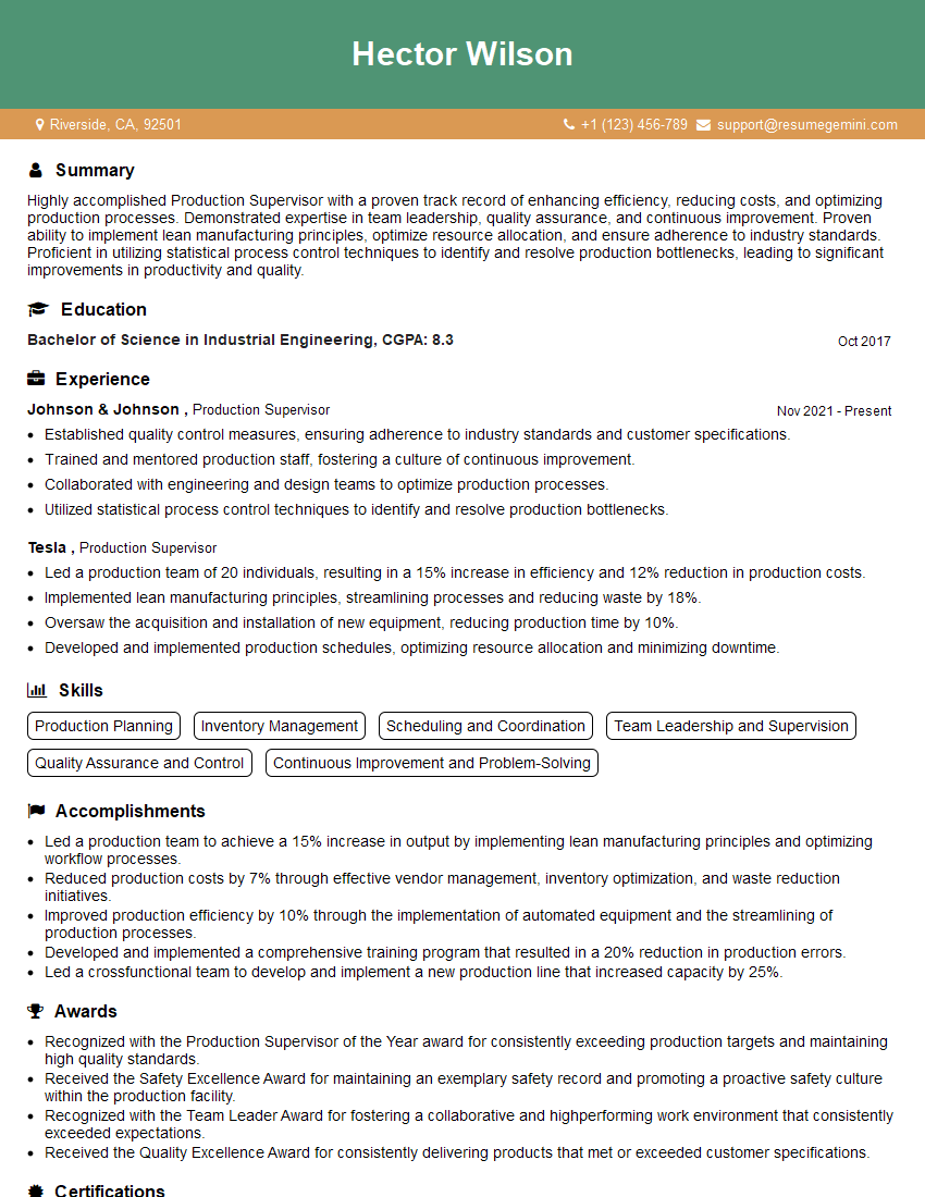
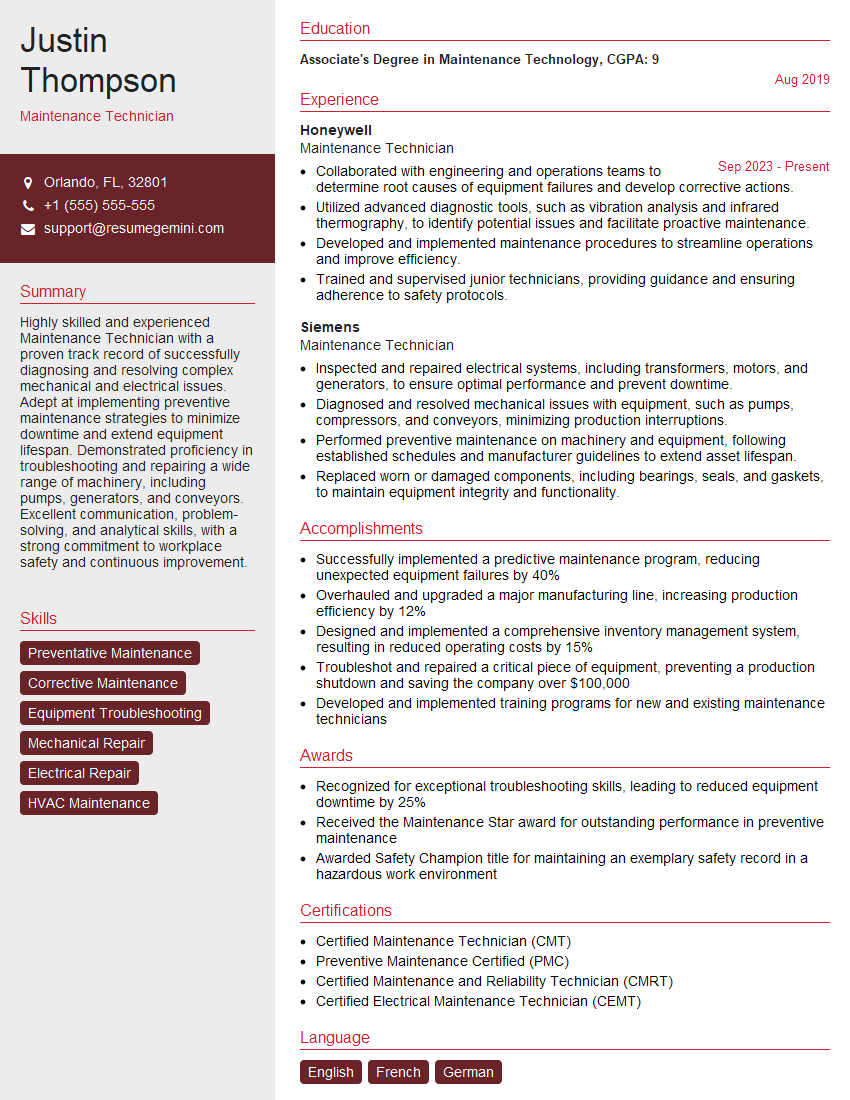
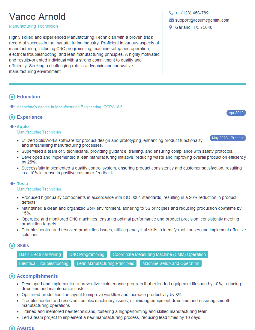
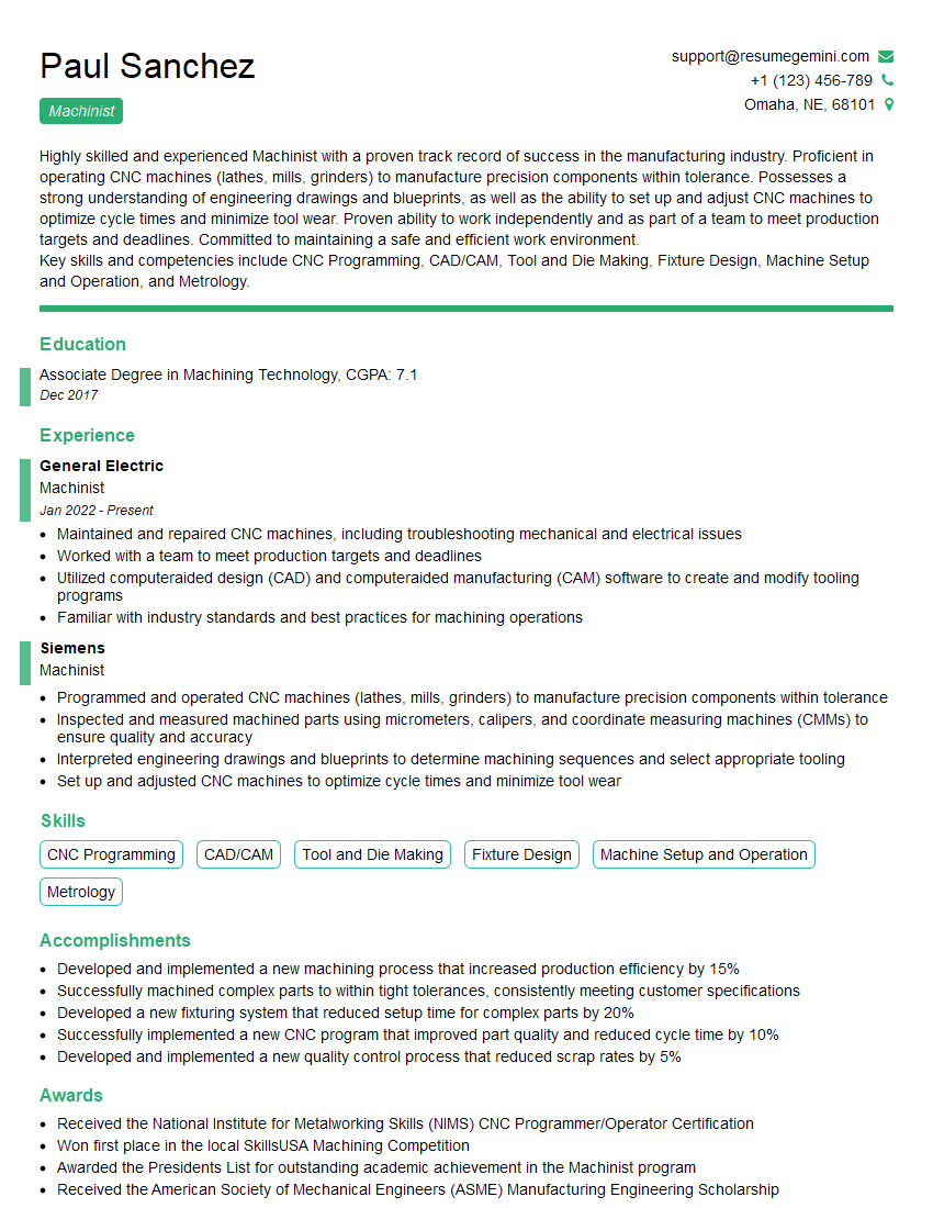
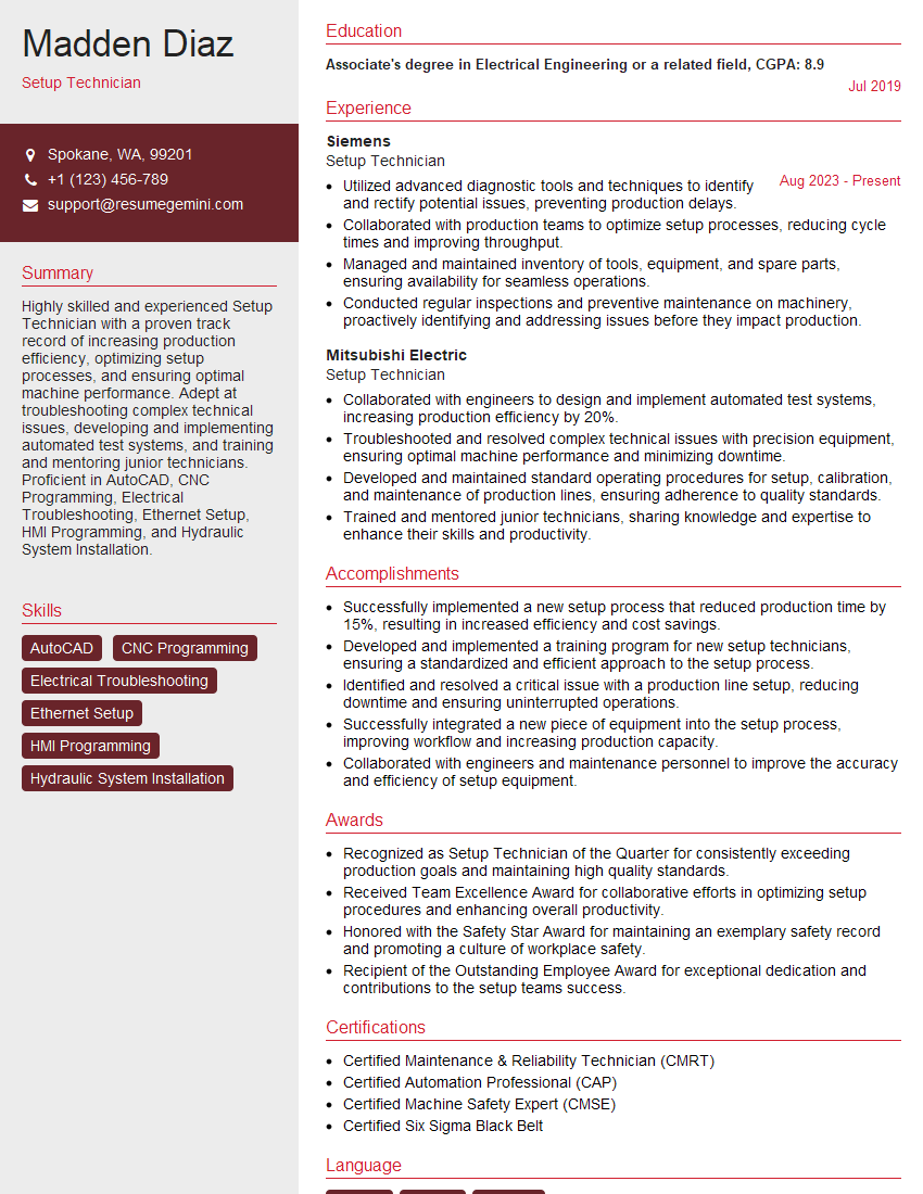
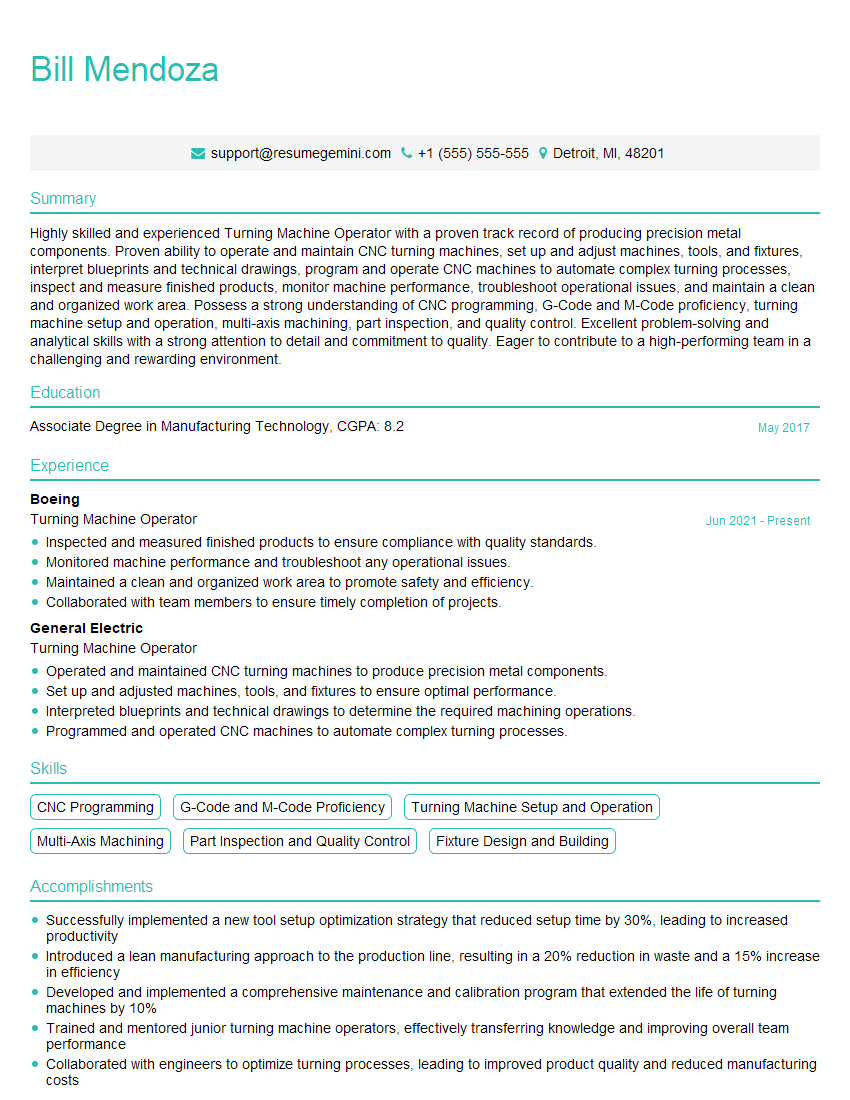
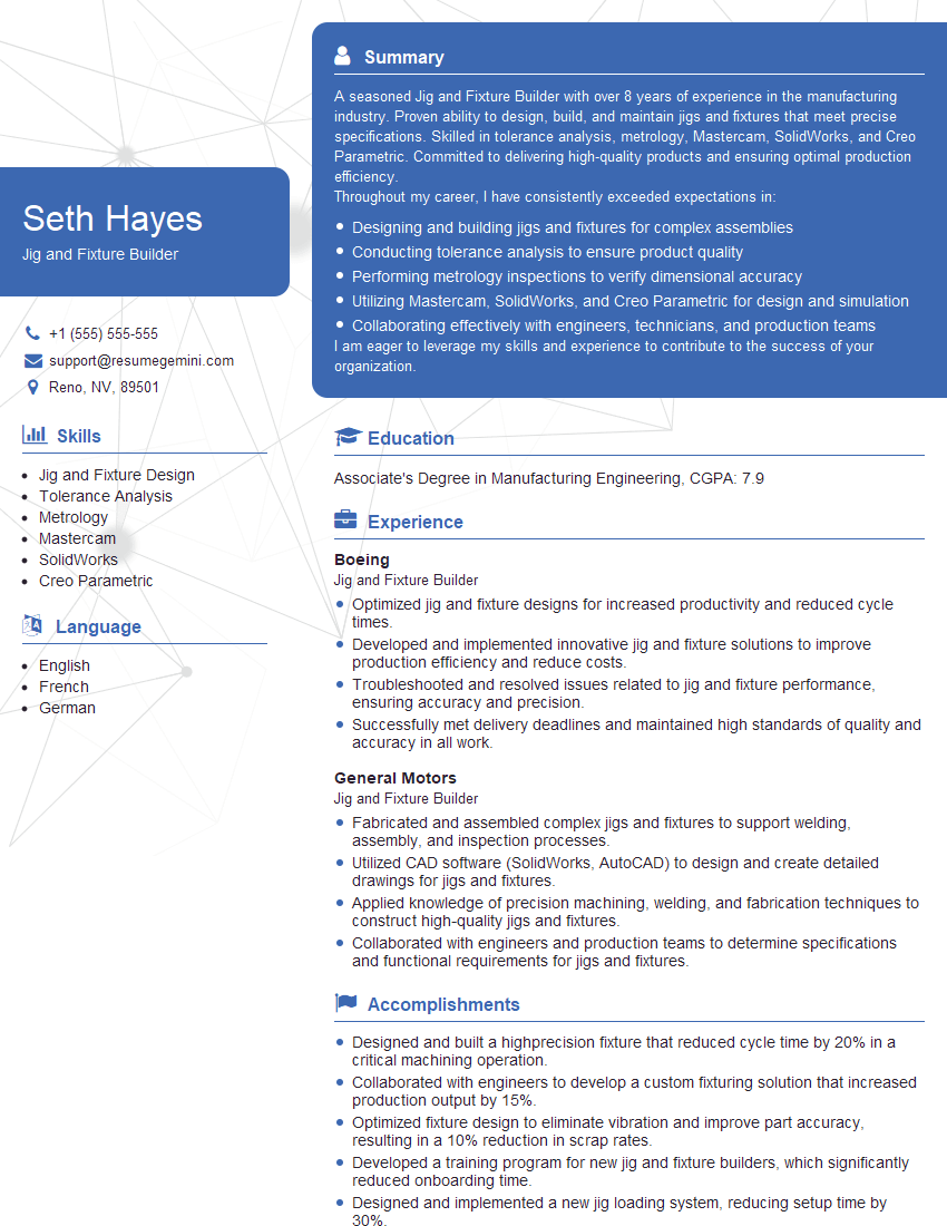
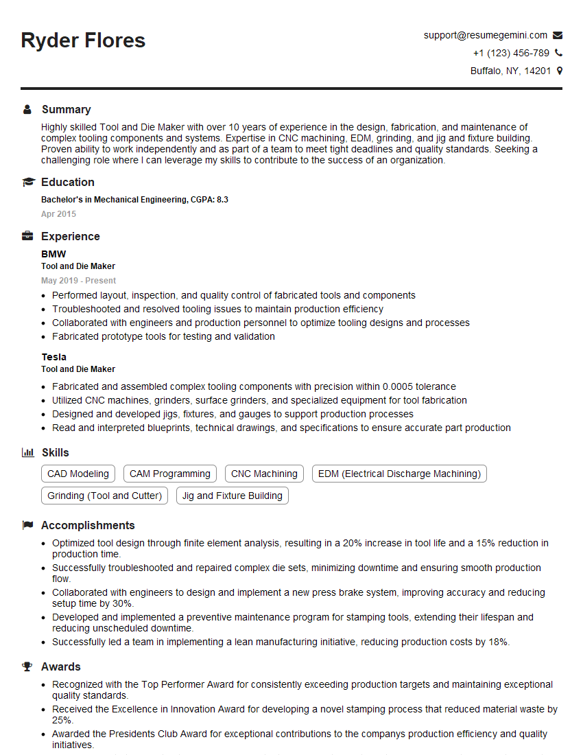
Mastering CNC, milling, and turning techniques opens doors to exciting career opportunities in manufacturing and engineering. A strong understanding of these skills makes you a highly valuable asset to any company. To maximize your job prospects, creating an ATS-friendly resume is crucial. ResumeGemini can help you build a professional, impactful resume that highlights your skills and experience effectively. Examples of resumes tailored to machining (CNC, milling, and turning) are available to guide you.
Explore more articles
Users Rating of Our Blogs
Share Your Experience
We value your feedback! Please rate our content and share your thoughts (optional).
What Readers Say About Our Blog
Interesting Article, I liked the depth of knowledge you’ve shared.
Helpful, thanks for sharing.
Hi, I represent a social media marketing agency and liked your blog
Hi, I represent an SEO company that specialises in getting you AI citations and higher rankings on Google. I’d like to offer you a 100% free SEO audit for your website. Would you be interested?
