Cracking a skill-specific interview, like one for Electronics Troubleshooting and Repair, requires understanding the nuances of the role. In this blog, we present the questions you’re most likely to encounter, along with insights into how to answer them effectively. Let’s ensure you’re ready to make a strong impression.
Questions Asked in Electronics Troubleshooting and Repair Interview
Q 1. Describe your experience with diagnosing faulty components in electronic circuits.
Diagnosing faulty components starts with a systematic approach. I begin by visually inspecting the circuit board for any obvious signs of damage like burnt resistors, swollen capacitors, or broken traces. Then, I use a multimeter to measure voltages and resistances at various points in the circuit, comparing these readings to the expected values based on the schematic. If a component’s measured value significantly deviates from the expected value, it’s a strong indicator of a fault. For example, if a resistor is supposed to be 1kΩ but measures as an open circuit, it’s clearly faulty. I also employ techniques like signal tracing to isolate the faulty section. In more complex circuits, I might use an oscilloscope to observe waveforms and identify problems in timing or signal integrity. Finally, if the fault isn’t immediately obvious, I’ll use a process of elimination, systematically testing components until the faulty one is identified. A challenging case involved a faulty audio amplifier where the output was distorted. By carefully measuring the bias voltages and observing the waveforms using an oscilloscope, I pinpointed the issue to a failing operational amplifier which was subsequently replaced, restoring normal function.
Q 2. Explain the process of using a multimeter to troubleshoot a circuit.
The multimeter is an indispensable tool. Before starting, always ensure the multimeter is set to the correct function and range to avoid damage. The process involves several steps: First, I visually inspect the circuit to understand its layout and identify points of interest. Then, I use the multimeter’s voltage function (DC and AC) to measure voltages across various components to verify they are within expected ranges. Next, I use the resistance function to check for shorts or opens in components or circuit paths. I’ll often disconnect the power to the circuit before measuring resistance to ensure accurate results. For instance, a high resistance reading across a capacitor might indicate a leaky or open capacitor. Continuity testing is used to check for broken traces on PCBs. Finally, I use the current function carefully and sparingly, especially in active circuits, to measure current flow through components. Always remember safety first: Disconnect power before testing, and double-check your settings to avoid damaging the meter or the circuit under test.
Q 3. How do you identify and replace surface mount components?
Identifying surface mount components (SMCs) requires a keen eye and the right tools. They are much smaller than through-hole components, often requiring magnification. The components are usually marked with alphanumeric codes that indicate their value and type. A datasheet or component identification tool can be invaluable here. Removing SMCs requires specialized tools such as a hot air rework station or a soldering iron with a fine tip. Before attempting removal, I thoroughly clean the area and ensure proper grounding to prevent static electricity damage. The hot air station provides controlled heat for careful removal, preventing damage to surrounding components. For smaller components, I might use fine tweezers to gently lift the component after softening the solder. After removal, I clean the pads using solder wick or specialized cleaning tools. Replacing involves applying a small amount of solder paste to the pads before carefully positioning the new component. Then, I use a soldering iron to reflow the solder, ensuring a good connection. It’s essential to use appropriate heat and avoid overheating the components or board.
Q 4. What are common soldering techniques and when would you use each?
Several soldering techniques exist, each suited for different tasks. For through-hole components, I typically use a through-hole soldering technique applying solder to the component lead and the PCB pad simultaneously. For surface mount components, I use either a reflow technique with a hot air station or a surface mount soldering technique where solder paste is applied, and the component is placed before reflowing the solder using a soldering iron. Iron-to-iron soldering is suitable for specialized cases involving joining wires, and it involves simultaneously heating the components to be soldered. The choice of technique depends on the component type, size, and the circuit complexity. Using the right technique ensures a strong and reliable connection, preventing cold solder joints or shorts. Poor soldering is a common cause of circuit malfunctions, so precision and cleanliness are vital.
Q 5. How do you interpret circuit diagrams and schematics?
Interpreting circuit diagrams and schematics is fundamental. A schematic is a symbolic representation of a circuit, showing the components and their interconnections. I begin by understanding the symbols used, which represent different components like resistors, capacitors, transistors, and integrated circuits. I trace the signal flow to understand the circuit’s functionality. I pay close attention to the values of components, node voltages and ground references. Understanding the circuit’s overall function, the roles of individual components and tracing signal paths from input to output are key to troubleshooting effectively. For example, identifying feedback loops in amplifiers or the clock signal path in digital circuits are crucial for diagnosing issues. A well-annotated schematic greatly assists in understanding the design intent, which makes troubleshooting more efficient. I often use a combination of the schematic and the physical circuit board to ensure accurate diagnosis.
Q 6. Explain your experience with troubleshooting analog and digital circuits.
My experience encompasses both analog and digital circuits. Analog troubleshooting involves measuring voltages, currents, and waveforms using multimeters and oscilloscopes to identify issues like signal distortion, noise, or incorrect bias points. Digital troubleshooting often involves using logic analyzers and probes to observe the digital signals and identify timing errors, logic level issues, or data corruption. For example, identifying a stuck-at-0 or stuck-at-1 fault in a digital circuit requires careful signal tracing and the use of logic analyzers. Analog circuits may exhibit issues such as drift, offset voltage, and nonlinear behavior, requiring different measurement techniques. I am proficient in using specialized test equipment tailored to each circuit type and adapting my approach according to the specific characteristics of the circuit.
Q 7. Describe your experience with troubleshooting power supplies.
Troubleshooting power supplies requires careful attention to safety. I always start with a visual inspection, checking for any obvious signs of damage, such as burnt components or loose connections. Then, using a multimeter, I measure the input voltage to ensure it is correct. Next, I measure the output voltage under various load conditions to verify if it meets the specifications. If the output voltage is incorrect, I check the feedback circuitry and the voltage regulation components (like transistors, zener diodes and op amps). I also measure the current draw to identify potential shorts or overloads. Furthermore, I carefully observe the ripple voltage in the output to check if the filtering is functioning correctly. One time, I had to diagnose a failing switching power supply. By systematically measuring voltages at different stages and using an oscilloscope to analyze the switching waveforms, I identified a faulty switching transistor and replaced it, resolving the problem.
Q 8. How familiar are you with different types of oscilloscopes and their applications?
Oscilloscopes are indispensable tools for visualizing and analyzing electronic signals. My experience encompasses various types, including analog, digital storage oscilloscopes (DSOs), and mixed-signal oscilloscopes (MSOs).
- Analog oscilloscopes: These display the signal waveform directly on a CRT screen. They’re excellent for observing signal shape and frequency, but lack the advanced features of DSOs.
- Digital Storage Oscilloscopes (DSOs): DSOs capture and store the waveform digitally, allowing for detailed analysis, measurements, and post-processing. This is crucial for intermittent faults, where a signal may not consistently appear.
- Mixed-Signal Oscilloscopes (MSOs): MSOs combine the capabilities of a DSO with a logic analyzer, enabling simultaneous viewing of both analog and digital signals. This is incredibly helpful in debugging complex digital circuits where analog signals influence digital behavior.
For instance, while troubleshooting a power supply, an oscilloscope would allow me to observe the voltage waveform and identify any ripple, spikes, or other irregularities indicative of a problem. Similarly, when working with microcontroller systems, an MSO would let me see both the digital control signals and the corresponding analog sensor readings.
Q 9. How do you diagnose and repair problems with printed circuit boards (PCBs)?
Diagnosing PCB problems is a systematic process. I start with a visual inspection, checking for obvious signs of damage like burnt components, broken traces, or physical stress. Then, I use a multimeter to check for continuity, voltage levels, and resistance across key components and circuit paths.
For more complex problems, I employ a combination of techniques:
- In-circuit testing: Using a multimeter or specialized test equipment to measure signals at various points on the board while the circuit is powered.
- Signal tracing: Following the signal path with an oscilloscope to pinpoint where a signal deviates from the expected behavior.
- Component-level testing: Removing and testing individual components (resistors, capacitors, integrated circuits) using a multimeter, component tester, or even a curve tracer for more thorough analysis.
- Thermal imaging: Identify overheating components that might be failing or are under stress.
Once the faulty component or circuit path is identified, I use appropriate techniques like soldering or desoldering to replace or repair it. Proper documentation of the repair process is essential for future reference and traceability.
Q 10. What are some common causes of electronic component failures?
Electronic component failures are often caused by a combination of factors. Here are some common causes:
- Overheating: Excessive heat generated by the component due to overcurrent, poor heat dissipation, or faulty design. This is frequently seen with power transistors and integrated circuits.
- Overvoltage/Undervoltage: Components receiving a voltage outside their operational range, which can lead to immediate failure or gradual degradation.
- Overcurrent: More current than the component’s rating flows through it, leading to excessive heat and potential damage. Short circuits are a primary cause of this.
- Electrostatic discharge (ESD): Static electricity can damage sensitive electronic components, particularly integrated circuits.
- Age and wear: Components degrade over time, eventually reaching end-of-life and causing failures. Capacitors exhibiting reduced capacitance or increased ESR are common examples.
- Manufacturing defects: Some components might fail due to imperfections in the manufacturing process. This is statistically rare but cannot be entirely ruled out.
For example, a capacitor failing in a power supply due to aging could lead to erratic voltage regulation, while a transistor failure in an amplifier might result in distorted audio output.
Q 11. Describe your experience using specialized test equipment (e.g., logic analyzers, function generators).
I have extensive experience using various specialized test equipment. My expertise includes:
- Logic analyzers: These are invaluable for debugging digital circuits by capturing and displaying the digital signals present on multiple lines. I’ve used logic analyzers extensively in debugging microcontroller-based systems, identifying timing issues, protocol violations, and glitches within data streams.
- Function generators: These instruments generate various waveforms (sine, square, triangle, etc.) with adjustable frequency, amplitude, and offset. I frequently use them to test the response of circuits to specific input signals during design and troubleshooting stages. For example, I can use a function generator to inject a sine wave into an amplifier and observe the output on an oscilloscope to check for gain and distortion.
One recent project involved using a logic analyzer to debug a communication protocol issue in an industrial control system. The logic analyzer allowed me to visualize the data bus signals and identify a timing discrepancy that was causing intermittent failures.
Q 12. How do you troubleshoot intermittent faults in electronic equipment?
Troubleshooting intermittent faults is challenging because the problem isn’t consistently reproducible. My approach involves a combination of techniques:
- Stress testing: Subjecting the equipment to conditions that might trigger the fault (temperature variations, vibration, power cycling). This can help to reproduce the fault more reliably.
- Observation and monitoring: Closely observing the system while it operates, looking for any patterns or conditions that precede the fault. This might involve temperature monitoring, voltage monitoring, or even visual inspection of component behavior.
- Data logging: If possible, logging system parameters over extended periods of time can help reveal patterns associated with the intermittent fault. This may involve data acquisition systems or specialized software.
- Reflow techniques: For surface-mount technology (SMT) components, reflowing the solder joints can temporarily fix cold solder joints which can cause intermittent issues.
Remember, patience and meticulous attention to detail are crucial when dealing with intermittent problems.
Q 13. How familiar are you with ESD (Electrostatic Discharge) safety precautions?
ESD safety is paramount in electronics repair. I am thoroughly familiar with ESD precautions and always follow them meticulously. This includes:
- ESD-safe work surfaces: Using anti-static mats and wrist straps connected to a grounded point.
- ESD-safe clothing: Avoiding clothes made from materials that generate static electricity.
- Proper handling techniques: Using anti-static bags to store and transport sensitive components. Grounding myself and any tools before handling sensitive components.
- Ionizers: Using air ionizers to neutralize static charges in the work area.
Ignoring ESD precautions can lead to irreparable damage to sensitive components, resulting in unnecessary costs and delays. I always prioritize ESD safety to protect the devices I am working on and to protect myself from potential shocks.
Q 14. Explain your experience with repairing various types of electronic devices (e.g., computers, smartphones, industrial equipment).
My experience spans a wide range of electronic devices. I’ve repaired:
- Computers: From troubleshooting motherboard issues and power supply problems to replacing hard drives and memory modules.
- Smartphones: Diagnosing and repairing screen damage, battery replacements, and logic board repairs, understanding complex SoC (System on a Chip) architecture.
- Industrial equipment: Working on programmable logic controllers (PLCs), motor drives, sensor systems, and other industrial control systems. This often involves working with high voltages and safety-critical systems.
A memorable experience involved repairing a critical piece of industrial equipment that controlled a manufacturing process. The failure led to significant production downtime. Through systematic troubleshooting and component-level repair, I was able to restore the equipment quickly, minimizing production losses. My experience in diverse areas allows for a comprehensive approach to diagnostics and repair.
Q 15. Describe your troubleshooting process for a system exhibiting unexpected behavior.
My troubleshooting process follows a systematic approach, much like a detective investigating a crime scene. It starts with observation and a clear understanding of the expected behavior of the system. Then, I compare this to the actual behavior to pinpoint the discrepancy. This is followed by a structured process:
- Gather Information: I begin by asking questions. What exactly is wrong? When did it start? Were there any recent changes to the system? This initial information gathering can often narrow down the possibilities significantly.
- Visual Inspection: A thorough visual inspection is crucial. Look for obvious signs of damage, loose connections, burnt components, or anything out of the ordinary. Sometimes a simple visual check solves the problem immediately.
- Isolate the Problem: Once I have a general idea of the problem area, I isolate the faulty component or section. This often involves removing and testing individual components or modules.
- Testing and Verification: Using appropriate test equipment like multimeters, oscilloscopes, and logic analyzers, I test the suspected components and circuits to verify their functionality. I often use a ‘divide and conquer’ approach. For instance, if a circuit board has several sections, I’ll isolate each section and test it until I find the source of the issue.
- Repair or Replacement: Once the faulty component is identified, I repair it if possible, or replace it with a known good part. If the fault is a more complex circuit issue, schematic analysis may be required.
- Verification and Documentation: After repair or replacement, I retest the system to ensure the problem is resolved. A final test is conducted to check if the system functions as intended. Crucially, I always document all my findings.
For example, if a computer won’t power on, I would start by checking the power supply, then the motherboard, and then progress systematically through other components. This systematic method ensures efficiency and minimizes the time taken.
Career Expert Tips:
- Ace those interviews! Prepare effectively by reviewing the Top 50 Most Common Interview Questions on ResumeGemini.
- Navigate your job search with confidence! Explore a wide range of Career Tips on ResumeGemini. Learn about common challenges and recommendations to overcome them.
- Craft the perfect resume! Master the Art of Resume Writing with ResumeGemini’s guide. Showcase your unique qualifications and achievements effectively.
- Don’t miss out on holiday savings! Build your dream resume with ResumeGemini’s ATS optimized templates.
Q 16. How do you document your troubleshooting steps and findings?
Documentation is paramount in electronics troubleshooting. It ensures reproducibility and facilitates future repairs. My documentation includes:
- Detailed Description of the Problem: A precise explanation of the malfunction, including any error messages or unusual behaviors.
- Steps Taken: A chronological record of every step I take during the troubleshooting process, noting the test equipment used, measurements obtained, and observations made. This includes successful and unsuccessful tests. This provides a clear and easily revisitable trail of actions taken.
- Schematic Diagrams (if available): Highlighting the tested circuits and the results of tests performed. Hand-drawn sketches are suitable in the absence of original schematics.
- Measurements and Readings: Specific values obtained using multimeters, oscilloscopes etc., with units clearly indicated (e.g., ‘Voltage across R1: 3.3V’). This is extremely important for confirming and repeating the process.
- Component Identification and Replacement Information: Specifying any replaced components with their part numbers, manufacturers, etc.
- Photographs: Images of the faulty component, the circuit board, and any other relevant visual details are always helpful, especially for intricate boards.
- Conclusion: Summarising the cause of the failure and the corrective actions taken. This helps in establishing patterns, preventing future occurrences, and streamlining processes.
I usually maintain a digital log, often integrating images and measurements into a single document for easy access and sharing.
Q 17. How do you prioritize tasks when multiple pieces of equipment need repair?
Prioritizing repair tasks requires a combination of factors. I typically use a system that considers:
- Urgency: Equipment critical for ongoing operations (e.g., a server in a production environment) takes precedence over non-critical equipment.
- Impact: The potential disruption caused by a malfunction affects the priority. A malfunctioning safety system demands immediate attention.
- Repair Complexity: Simple repairs are tackled first, freeing up time for more challenging ones.
- Parts Availability: If a repair requires a specific part that is difficult to source, it might be scheduled accordingly.
- Customer Impact: If the equipment failure affects a client, the urgency increases dramatically.
I often use a ticketing system to track tasks, assigning priorities and deadlines. This provides a visual representation of the workload and aids in managing time efficiently.
Q 18. What are your preferred methods for tracing signals in a circuit?
Tracing signals is a fundamental skill. My preferred methods depend on the complexity of the circuit and the available equipment:
- Oscilloscope: For examining waveforms, identifying signal levels, and determining frequency and timing. It’s crucial for analyzing analog and digital signals.
- Logic Analyzer: Specifically for digital circuits, analyzing multiple digital signals simultaneously to understand the logic flow.
- Multimeter: Measures voltage, current, and resistance. Helpful for identifying open circuits, shorts, and verifying power supply voltages. This can sometimes be enough for simple circuits.
- Current Probes: Measure current directly in a circuit without breaking the circuit. This is incredibly useful, as it is non-invasive and helps avoid problems with introducing new faults while troubleshooting.
- Signal Generators/Function Generators: Used to inject signals into the circuit for testing. Very useful when performing active testing in a circuit.
- Schematic Diagram Analysis: Understanding the circuit’s design is paramount. Following the signal path on a schematic helps in focusing tests effectively.
For example, to trace a faulty signal in a microcontroller circuit, I would start by checking the input pins on the microcontroller using a logic analyzer to see if the signal reaches the chip correctly. If not, I would trace the signal back along the circuit board to identify the point of failure.
Q 19. Explain your understanding of different types of electronic components (e.g., resistors, capacitors, transistors).
Understanding electronic components is essential. Here’s a summary:
- Resistors: These components restrict the flow of current. They’re defined by their resistance (measured in ohms) and power rating (measured in watts). Different types exist, like carbon film, metal film, and wire-wound, each with different characteristics.
- Capacitors: These store electrical energy. They’re characterized by their capacitance (measured in farads), voltage rating, and type (e.g., ceramic, electrolytic, film). Capacitors play a vital role in filtering and timing circuits.
- Transistors: These are semiconductor devices acting as electronic switches or amplifiers. Common types include bipolar junction transistors (BJTs) and field-effect transistors (FETs). BJTs control current flow by a smaller current signal, while FETs control current flow by voltage levels.
- Integrated Circuits (ICs): These contain complex circuits on a single chip. Their functionality is highly specialized, from simple logic gates to microprocessors and memory chips.
- Diodes: These are one-way devices allowing current to flow in one direction only. Commonly used for rectification and protection.
- Inductors: These store energy in a magnetic field. They’re characterized by their inductance (measured in henries) and used in filters and power supplies.
Understanding the function and characteristics of these components is key to effective troubleshooting. Incorrect voltage or current levels in a circuit can often be traced to component failure.
Q 20. How do you handle situations where you are unable to diagnose a problem?
When I’m stumped, I employ several strategies:
- Consult Resources: I refer to datasheets, schematics, application notes, and online forums for information relating to the specific components and circuit design. Datasheets are incredibly valuable.
- Seek Expert Advice: If I need a second opinion, I consult with more experienced colleagues or specialists. Sometimes a fresh perspective provides the breakthrough.
- Systematic Testing and Elimination: I carefully review the steps I’ve already taken, ensuring thoroughness. I may also try different test methods or equipment.
- Signal Tracing: A detailed examination of the signal path, using the tools I’ve mentioned earlier.
- Simulate the Circuit: If a circuit is particularly complex, simulation tools can help identify potential problems before further physical testing.
- Fault Injection: (Used cautiously and when appropriate) Intentionally introducing faults in the circuit to observe how the system reacts can reveal the location of a hidden problem.
It’s important to acknowledge when you’ve reached the limit of your expertise, and seek help or admit that further investigation is required.
Q 21. What safety measures do you take when working with high-voltage circuits?
Safety is paramount when dealing with high-voltage circuits. My safety measures include:
- Proper Training: I have received comprehensive training in high-voltage safety procedures.
- Personal Protective Equipment (PPE): I always use appropriate PPE, including insulated gloves, safety glasses, and insulated tools. The correct PPE for the voltage is crucial.
- Lockout/Tagout Procedures: Before working on any high-voltage circuit, I ensure power is completely isolated using lockout/tagout procedures to prevent accidental energization. This is essential.
- Double Checking: I always double-check the power is off using a reliable voltage tester before touching any component.
- Grounding: I ensure proper grounding to prevent static electricity discharge or build-up.
- Awareness of Potential Hazards: I’m always aware of potential hazards, like arc flashes, and take appropriate precautions.
- Working with a Partner: For high-voltage work, I prefer to have a partner present for added safety and assistance.
Safety is not optional; it’s a fundamental aspect of responsible high-voltage work. Taking shortcuts can lead to serious injury or even death.
Q 22. Describe your experience with data acquisition and analysis tools.
Data acquisition and analysis are crucial for effective electronics troubleshooting. My experience encompasses using a wide range of tools, from simple multimeters and oscilloscopes to sophisticated logic analyzers and spectrum analyzers. I’m proficient in using software like LabVIEW, MATLAB, and specialized data acquisition software to capture, process, and interpret signals. For instance, when troubleshooting a faulty power supply, I’d use an oscilloscope to examine the voltage waveform for irregularities, like excessive ripple or noise, indicating a problem with filtering components. Then, I’d use a multimeter to measure voltages and currents at various points to pinpoint the faulty component. With more complex systems, LabVIEW would allow me to automate the data acquisition process, log data over time, and perform advanced analysis like FFTs to identify frequency-domain issues.
Furthermore, I’m experienced with using data logging systems to monitor parameters over extended periods to uncover intermittent faults. For example, I once used a data logger to track the temperature of a motor controller over several weeks to identify a thermal overload problem that only occurred under specific operating conditions. This highlighted the importance of using the right tool for the job and thoroughly analyzing the collected data to reach an accurate diagnosis.
Q 23. How do you stay updated on the latest advancements in electronics troubleshooting and repair?
The field of electronics is constantly evolving, so continuous learning is essential. I stay updated through several avenues. I regularly subscribe to and read industry publications like EDN and Electronic Design, attending webinars and online courses offered by organizations such as IEEE and various manufacturers. Active participation in online forums and communities dedicated to electronics troubleshooting is also valuable; it allows for collaborative problem-solving and exposure to different perspectives. Finally, I actively seek out opportunities to work with new technologies and components, embracing hands-on experience as a primary method of learning and adaptation. This practical approach helps me bridge the gap between theoretical knowledge and real-world applications.
Q 24. How familiar are you with different types of electronic packaging and assembly techniques?
My familiarity with electronic packaging and assembly techniques spans a wide range of methods. I’m experienced with through-hole technology (THT), surface-mount technology (SMT), and various PCB construction techniques. I understand the implications of different packaging choices on factors like thermal management, signal integrity, and reliability. For example, I know the importance of proper thermal vias in high-power SMT designs to prevent overheating. I’m also familiar with different types of enclosures, including metal, plastic, and specialized shielding for EMI/RFI reduction. My experience includes working with both manual and automated assembly processes, understanding the challenges and limitations of each. I’ve even had experience with specialized packaging like conformal coating and potting for harsh environmental applications. This knowledge helps in identifying potential failure points during troubleshooting based on the assembly method and chosen packaging.
Q 25. What is your experience with schematic capture and PCB design software?
I have extensive experience with schematic capture and PCB design software. My proficiency includes using industry-standard tools like Altium Designer, Eagle, and KiCad. I can create schematics from scratch, perform component placement and routing, and generate manufacturing files for PCB fabrication. I understand the importance of proper design practices for signal integrity, impedance matching, and EMI/RFI control. For example, I’ve designed PCBs for high-speed digital circuits, incorporating features like controlled impedance traces and proper grounding techniques to minimize signal reflections and crosstalk. I’m also familiar with using simulation tools to verify circuit performance before prototyping. This ability to design, simulate and troubleshoot circuits allows me to offer a holistic approach to resolving electronic problems.
Q 26. Explain your experience with troubleshooting embedded systems.
Troubleshooting embedded systems requires a systematic and methodical approach. My experience encompasses working with various microcontrollers and processors, from 8-bit to 32-bit architectures. I’m proficient in using JTAG debuggers and logic analyzers to analyze code execution, memory access, and I/O signals. I’m familiar with various debugging techniques such as breakpoint setting, single-stepping, and memory inspection. I also have experience with analyzing firmware, identifying memory leaks, and understanding the interaction between hardware and software. For example, I once had to track down a seemingly random reset in an embedded system, only to discover it was caused by a software bug that led to a stack overflow. My experience in firmware and hardware analysis allowed me to quickly identify and resolve the issue. I also understand the importance of utilizing documentation and understanding the system’s operational specifications to effectively isolate the source of the malfunction.
Q 27. Describe your experience working with different types of connectors and cables.
My experience with connectors and cables covers a broad range of types and applications. I’m familiar with various connector standards, including RJ45, USB, HDMI, DB9, and many others. I understand the importance of proper cable management and the impact of signal integrity on system performance. For instance, I’ve worked on projects requiring high-speed data transmission, understanding the importance of using shielded cables and proper termination to avoid signal reflections and crosstalk. I can identify and troubleshoot problems related to connector damage, loose connections, and incorrect wiring. My understanding extends to the physical characteristics of the cable, including impedance and shielding, helping me analyze cable-related signal integrity issues. This understanding is critical, especially when dealing with high-speed digital signals or sensitive analog signals where even minor imperfections can lead to major problems.
Q 28. How do you approach troubleshooting a complex system with multiple interconnected subsystems?
Troubleshooting complex systems requires a structured approach. My strategy typically involves a combination of top-down and bottom-up analysis. I begin with a thorough understanding of the system architecture, identifying individual subsystems and their interconnections. I’ll start by checking overall system functionality, then narrow the focus using a divide-and-conquer strategy. I might employ diagnostic tools to isolate faulty subsystems. For example, if a system shows no power, I would systematically check the power supply, then major power rails, before looking at specific boards. If multiple subsystems are suspected, I’d isolate them to test them individually. I’d use a combination of diagnostic software, logic analyzers, oscilloscopes, and multimeters to gather data from each subsystem. Detailed documentation and logging of each step are essential. Using clear documentation throughout the troubleshooting process is critical for ensuring accurate record-keeping and for future reference, also allowing others to understand the diagnostic process.
Key Topics to Learn for Electronics Troubleshooting and Repair Interview
- Digital Circuit Analysis: Understanding logic gates, Boolean algebra, and digital signal processing is fundamental. Practical application includes diagnosing faults in digital circuits found in computers and embedded systems.
- Analog Circuit Analysis: Mastering concepts like Ohm’s Law, Kirchhoff’s Laws, and amplifier circuits is crucial. Practical application involves troubleshooting audio equipment, power supplies, and sensor circuits.
- Soldering and Desoldering Techniques: Proficiency in these skills is essential for hands-on repair. Practical application involves replacing faulty components on circuit boards.
- Schematic Reading and Interpretation: Ability to understand and interpret electronic schematics is vital for identifying components and tracing signal paths. Practical application includes fault tracing and component identification.
- Troubleshooting Methodologies: Mastering systematic troubleshooting approaches like the “divide and conquer” method and using diagnostic tools is key. Practical application includes efficiently isolating and fixing problems in complex systems.
- Component Identification and Testing: Understanding the function and testing methods for various electronic components (resistors, capacitors, transistors, integrated circuits) is crucial. Practical application involves testing components with multimeters and other test equipment.
- Safety Procedures and Regulations: Knowledge of safety precautions and relevant regulations for working with electronics is paramount. Practical application includes safe handling of electrical equipment and avoiding hazards.
- Use of Diagnostic Equipment: Familiarity with oscilloscopes, multimeters, logic analyzers, and other diagnostic tools is essential for effective troubleshooting. Practical application involves using these tools to identify and analyze signals and component behaviour.
Next Steps
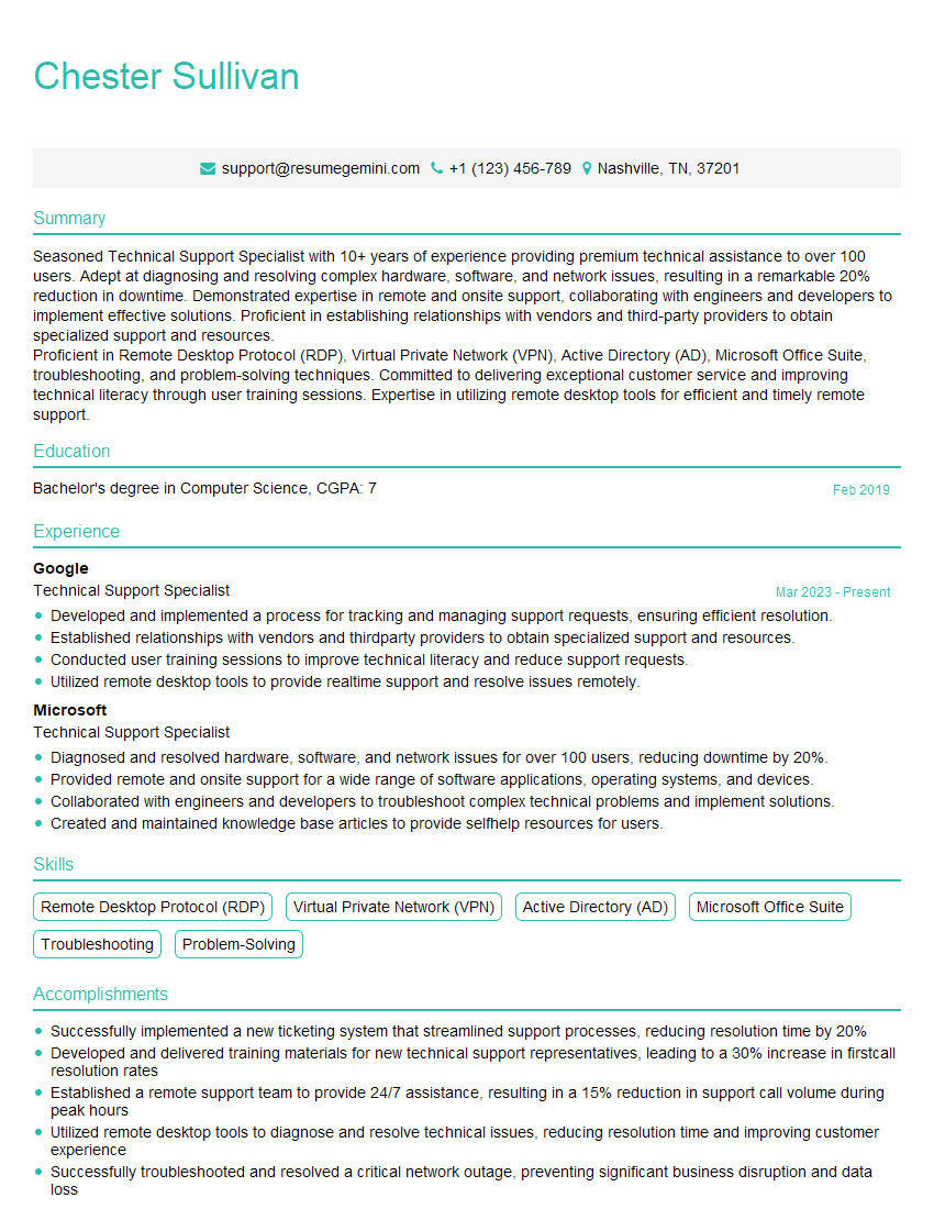
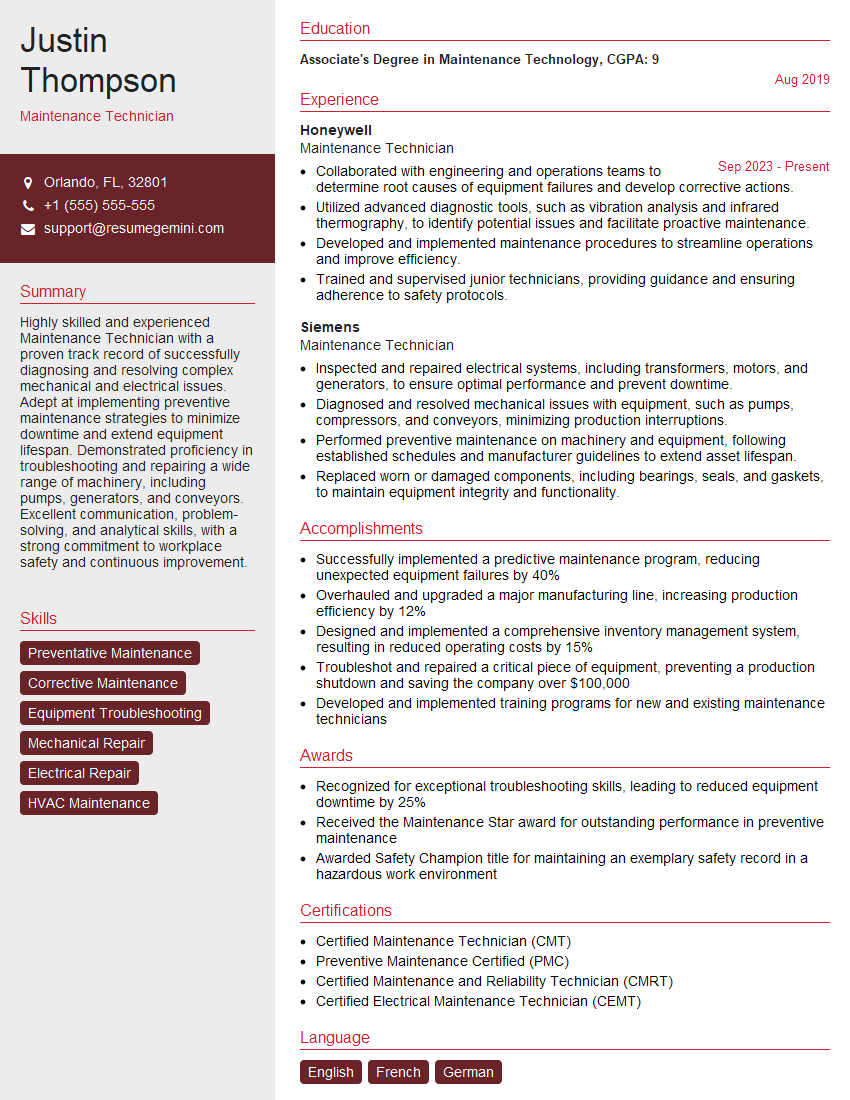
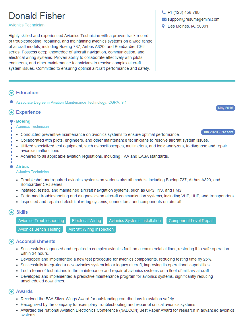
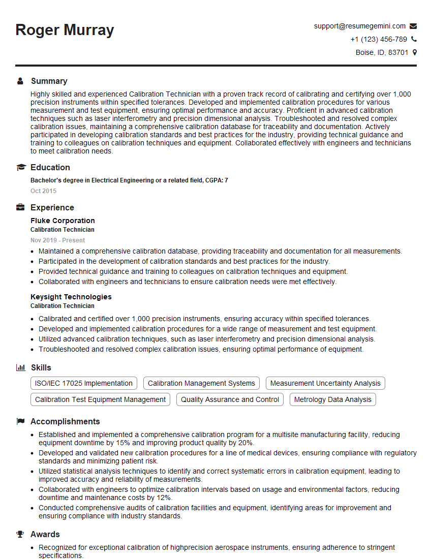
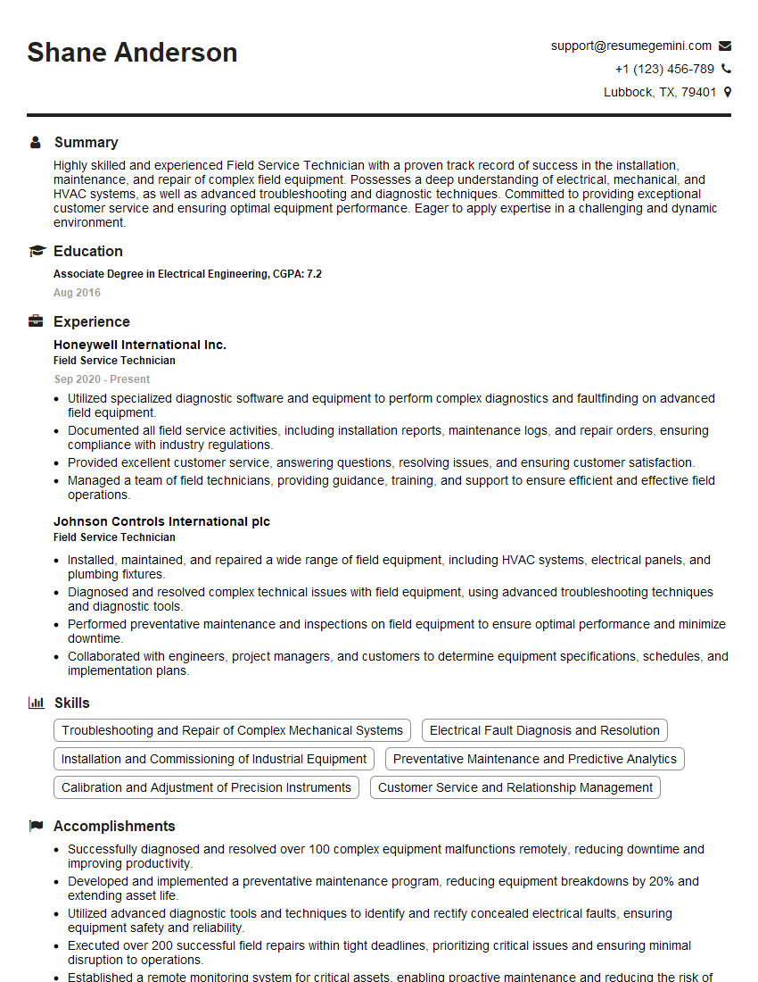
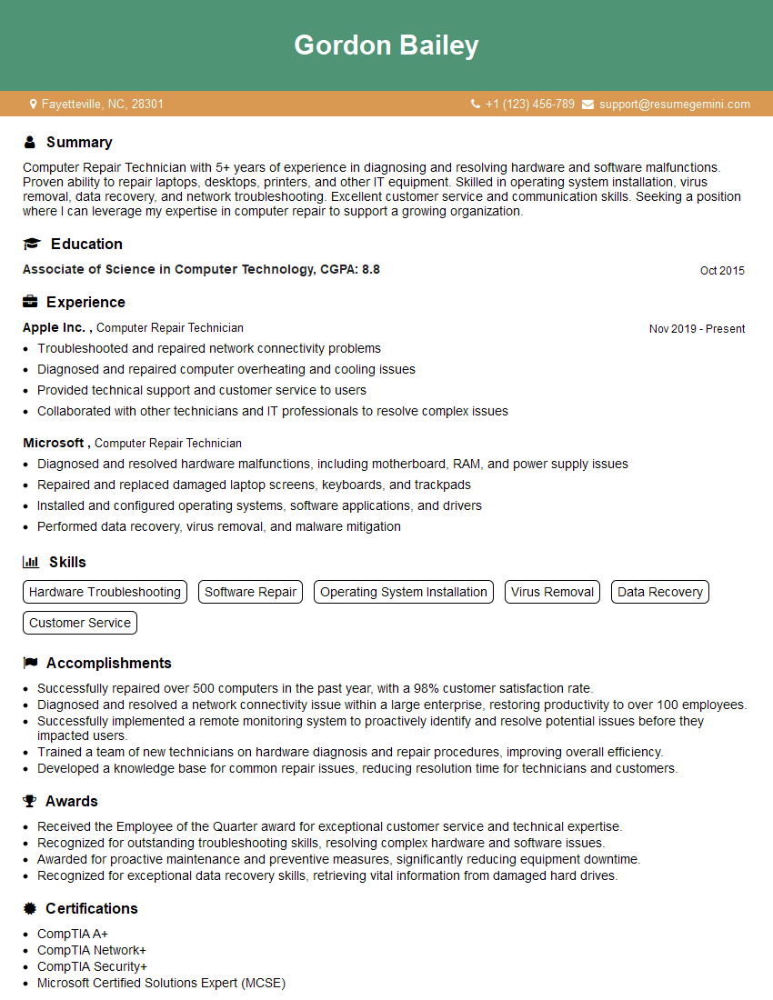
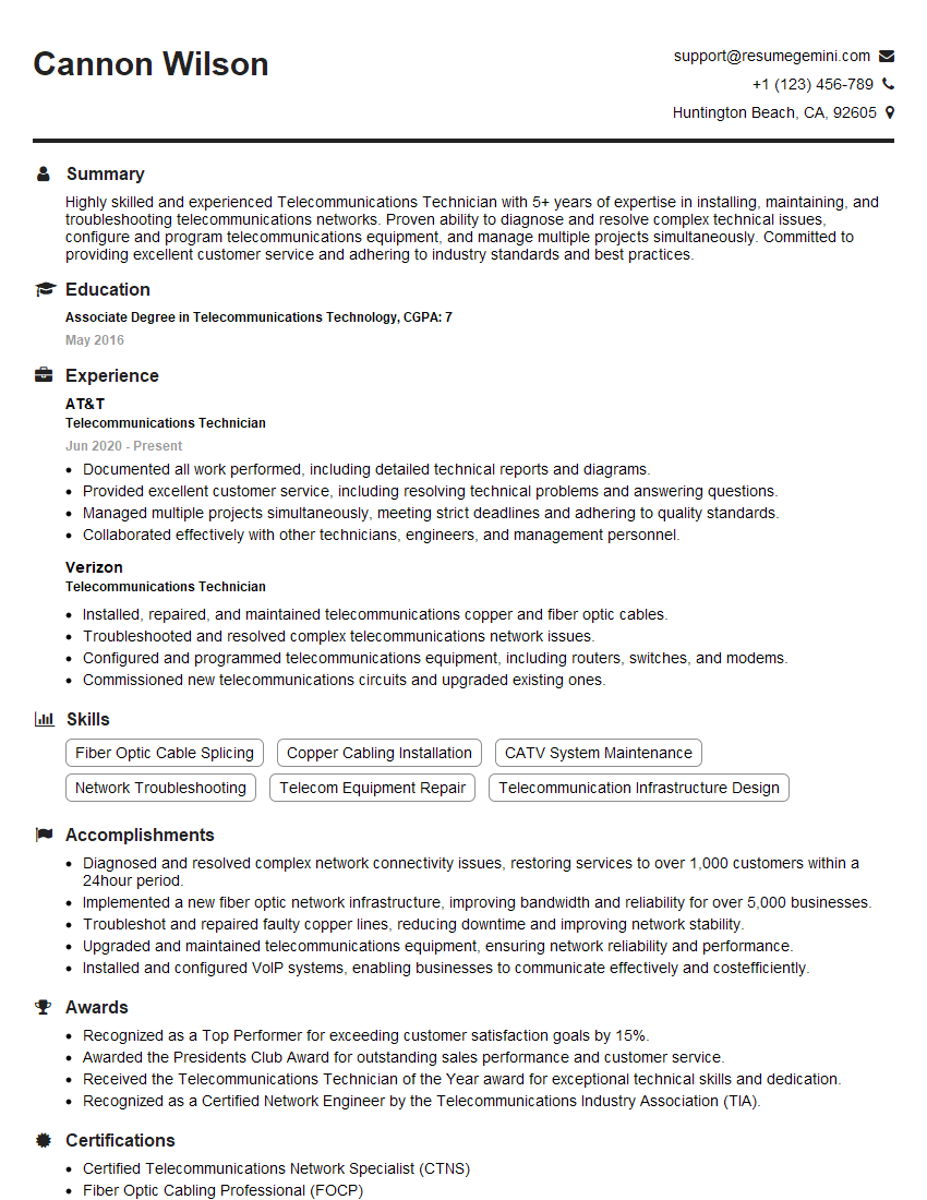
Mastering Electronics Troubleshooting and Repair opens doors to diverse and rewarding career opportunities in a constantly evolving technological landscape. A strong foundation in these skills translates to higher earning potential and increased job security. To significantly boost your job prospects, creating a well-structured, ATS-friendly resume is crucial. ResumeGemini is a trusted resource that can help you build a professional resume that highlights your skills and experience effectively. We provide examples of resumes tailored specifically to Electronics Troubleshooting and Repair to guide you through the process. Take the next step towards your dream career – build your best resume with ResumeGemini.
Explore more articles
Users Rating of Our Blogs
Share Your Experience
We value your feedback! Please rate our content and share your thoughts (optional).
What Readers Say About Our Blog
Live Rent Free!
https://bit.ly/LiveRentFREE
Interesting Article, I liked the depth of knowledge you’ve shared.
Helpful, thanks for sharing.
Hi, I represent a social media marketing agency and liked your blog
Hi, I represent an SEO company that specialises in getting you AI citations and higher rankings on Google. I’d like to offer you a 100% free SEO audit for your website. Would you be interested?
