Are you ready to stand out in your next interview? Understanding and preparing for SolidWorks and AutoCAD interview questions is a game-changer. In this blog, we’ve compiled key questions and expert advice to help you showcase your skills with confidence and precision. Let’s get started on your journey to acing the interview.
Questions Asked in SolidWorks and AutoCAD Interview
Q 1. Explain the difference between a part, assembly, and drawing in SolidWorks.
In SolidWorks, a part is the fundamental building block – a single, independent 3D model. Think of it as a single component like a bolt or a gear. An assembly is a collection of parts, assembled together to create a more complex structure, such as a complete bicycle or an engine. Finally, a drawing is a 2D representation of a part or assembly, providing information like dimensions, tolerances, and materials for manufacturing. It’s essentially the blueprint.
For example, you might create a part for a wheel, another for a frame, and then combine them in an assembly to represent a complete bicycle. A drawing would then detail the dimensions, materials, and assembly instructions for manufacturing.
Q 2. How do you create and manage layers in AutoCAD?
Layer management in AutoCAD is crucial for organizing complex drawings. Layers are like transparent sheets stacked on top of each other. Each layer can contain different elements, allowing you to control the visibility and properties of specific parts of your design.
You create a new layer using the LAYER command or through the Layers palette. You can assign properties to each layer, such as color, line weight, and linetype. This is essential for managing the complexity of a drawing. For example, you could have separate layers for architectural walls, electrical wiring, and plumbing fixtures, making it easier to edit and manage individual aspects of a building plan. You can also freeze or thaw layers to control their visibility, improving performance when working with large, detailed drawings. Layers are essential for collaborative work as well, allowing different team members to work on different aspects of a design simultaneously without interfering with each other’s work.
Q 3. Describe your experience with parametric modeling in SolidWorks.
Parametric modeling in SolidWorks is a powerful technique where you define a model using parameters (variables), rather than just defining its geometry directly. Changes to these parameters automatically update the entire model, maintaining design intent. This allows for rapid design iterations and easy modification.
In my experience, I’ve extensively used parametric modeling for various projects, including designing custom enclosures for electronics. By parameterizing dimensions like the enclosure’s length, width, and height, I could easily adjust the design to accommodate different components or optimize for manufacturing. For example, I might use a parameter for the thickness of the material, allowing me to quickly see how changes to material thickness affect the overall weight and strength of the enclosure. This significantly speeds up the design process and reduces the chances of errors compared to manually editing dimensions.
Q 4. What are the different types of constraints used in SolidWorks?
SolidWorks uses a wide variety of constraints to define relationships between features and components in a model. These constraints ensure that the model behaves as intended, maintaining geometric relationships even when parameters are changed.
- Mate Constraints: These define relationships between faces, edges, and points of different parts in an assembly (e.g., flush, concentric, parallel).
- Geometric Constraints: These define relationships between features within a part (e.g., parallel, perpendicular, tangent, concentric, equal distance).
- Dimensional Constraints: These define specific distances or angles within a part or assembly.
For example, when designing a table, you’d use mate constraints to connect the legs to the tabletop, ensuring they are perpendicular and properly aligned. Geometric constraints would help maintain symmetry and dimensional constraints would set the precise length and width of the table.
Q 5. How do you handle large assemblies in SolidWorks?
Managing large assemblies in SolidWorks requires strategies to improve performance and maintain design efficiency. Techniques I utilize include:
- Component simplification: Replacing detailed components with simplified representations when appropriate, improving loading times and reducing the complexity of the assembly.
- Lightweight components: Converting high-detail components to lightweight components, reducing file size and improving performance. These essentially retain the appearance of the model while reducing the computation load.
- Sub-assemblies: Breaking down large assemblies into smaller, more manageable sub-assemblies improves organization and performance. Each sub-assembly can be managed independently and later integrated into the main assembly.
- Large Assembly tools: Leveraging SolidWorks tools like the performance evaluation tools to identify and address bottlenecks in assembly performance.
A real-world example would be designing a car engine. Instead of modeling every single screw and nut individually, you might simplify many smaller parts into one unified component, thus significantly speeding up rendering time and the entire design process.
Q 6. Explain your experience with dimensioning and tolerancing in AutoCAD.
Dimensioning and tolerancing in AutoCAD are critical for communicating design intent and ensuring manufacturing accuracy. I have extensive experience in creating detailed drawings with accurate dimensions and tolerances using tools like the DIMSTYLE command to control dimension styles and the tolerance annotation tools.
Proper dimensioning ensures that all important measurements are clearly defined, and applying appropriate tolerances (e.g., +/- 0.1mm) communicates the acceptable range of variation for manufactured parts. This is crucial for ensuring that parts fit together correctly and function as intended. In a manufacturing setting, misinterpretations of dimensions or tolerances could be costly and time-consuming. For instance, in designing a precision instrument, incorrect tolerances might lead to malfunction and require significant rework. I ensure the precision and consistency of dimensions through a standardized dimensioning style throughout all the projects I have managed.
Q 7. How do you create and modify 3D models in SolidWorks?
Creating and modifying 3D models in SolidWorks involves a range of features and tools. The process generally starts by sketching 2D profiles, which are then extruded, revolved, or swept to create 3D features. Features can be added, subtracted, or modified using Boolean operations. SolidWorks’ feature-based modeling approach allows for easy modification of the model by changing features’ parameters or creating new ones.
For example, to create a simple box, you’d start by sketching a rectangle. Then, you’d use the extrude feature to give it depth, creating a 3D box. Adding holes or fillets is done by creating and applying the appropriate features, easily edited later on without rebuilding the entire model from scratch. I use this approach consistently for my design work, leveraging the power of features to model complex shapes and maintain clear design history.
Q 8. What are your preferred methods for creating 2D drawings from 3D models?
Creating 2D drawings from 3D models in SolidWorks is a streamlined process. My preferred method leverages SolidWorks’ built-in drawing functionality. I start by creating a new drawing document and inserting the 3D model. Then, I use the automated projection tools to create views – front, top, side, isometric, section views, and detail views as needed. This ensures accuracy and consistency. For complex assemblies, I strategically utilize configurations and design tables to generate multiple drawings efficiently. For example, creating drawings for different versions of a product based on minor design changes becomes simple. I also extensively use annotations like dimensions, tolerances, notes, and balloons to fully communicate design intent. Finally, I check and optimize the sheet layout for readability and clarity before saving it as a PDF or DWG for external use. This systematic approach avoids errors and guarantees clean, professional-looking 2D documentation.
Another valuable method, especially for creating detailed views, involves using section views and exploded views. For instance, when documenting a complex mechanism, an exploded view clearly shows the assembly sequence and relationships of individual components. Such techniques vastly improve communication to machinists or assembly personnel.
Q 9. How do you use rendering techniques in SolidWorks to enhance visualization?
SolidWorks offers a range of rendering techniques to enhance visualization, ranging from simple shaded views to photorealistic renderings. I frequently use PhotoView 360 for its ease of use and speed, especially in the early design stages. It allows for quick adjustments of lighting, materials, and environment to explore different aesthetics. For high-fidelity images, I utilize SolidWorks Visualize. Visualize boasts advanced rendering capabilities, offering realistic material properties, global illumination, and high-resolution output ideal for marketing materials or client presentations. A recent project involved showcasing a new product design. Using Visualize, I created stunning images that highlighted the product’s features and aesthetic appeal, which greatly assisted in securing client approval. I also utilize different rendering styles, like ‘realistic’, ‘shaded’, and ‘wireframe’, depending on the intended audience and purpose. For instance, wireframe rendering is useful for internal reviews, while realistic rendering works best for external presentations.
Q 10. Describe your experience using AutoCAD’s dynamic input features.
AutoCAD’s dynamic input is a cornerstone of my efficient workflow. It eliminates the need for constant cursor hovering over the command line, allowing for more intuitive and faster drawing. I rely heavily on its coordinate input and object snapping options. For example, I frequently use @ for relative coordinates to quickly sketch and position objects precisely. Object snaps like endpoint, midpoint, and intersection are indispensable for precise connections and relationships between elements. This significantly reduces the likelihood of errors. Dynamic input also provides real-time feedback on dimensions and angles as I draw. This constant visualization ensures accuracy and eliminates the need for later adjustments. Furthermore, I utilize polar tracking and orthogonal modes for precise angular and linear constructions. Imagine drawing a perfectly aligned rectangle quickly and without the need for repeated commands. That’s the power of dynamic input.
Q 11. How do you manage and organize large AutoCAD drawings?
Managing large AutoCAD drawings requires a structured approach. I utilize external references (xrefs) extensively to manage large projects. This allows me to break down a large drawing into smaller, more manageable files, each focused on a specific component or assembly. For organization, I employ a clear naming convention that reflects the project, drawing type, and revision number. Layer management is crucial. Each layer has a specific purpose and is used consistently throughout the project. This makes it easier to isolate and manipulate elements within the drawing. Purging unused blocks, layers, and other elements helps to maintain file size. Finally, I regularly back up my work and use version control to track changes and revert to previous versions if necessary. Regular purging and the use of external references have saved me countless hours of frustration, especially when working with intricate drawings containing hundreds of objects and layers.
Q 12. Explain your experience with different AutoCAD plotting configurations.
My experience with AutoCAD plotting configurations is extensive. I’m comfortable configuring plot styles to control line weights, colors, and linetypes to match specific plotters and standards. I frequently use named plot styles to maintain consistency across multiple drawings. Understanding the page setup manager is critical; I manage plot area, plot scale, plot offset, and paper size for optimized output. I often customize paper sizes and plot areas to meet specific requirements. I’ve also worked with various plotters and understand the nuances of different plot drivers and how to troubleshoot issues. For example, I once resolved a plotting issue caused by an outdated driver by installing the latest update, resulting in improved print quality and efficiency. Having expertise in plot configuration leads to high-quality, professional-looking drawings that meet specific client needs and industry standards.
Q 13. How proficient are you with SolidWorks Simulation?
My proficiency with SolidWorks Simulation is intermediate to advanced. I’m comfortable setting up and running static, dynamic, and fatigue studies. I can define materials, apply loads, and constrain models to accurately simulate real-world scenarios. I’ve used SolidWorks Simulation to analyze stress, strain, and displacement in various components, including a structural beam analysis project where I determined the maximum load-bearing capacity before failure, significantly aiding in the design optimization process. I understand the importance of meshing and its impact on accuracy, and I know how to refine mesh density in critical areas for better results. I’m adept at interpreting the results to make informed design decisions based on safety factors and performance requirements. While I haven’t conducted highly specialized simulations, I’m confident in my ability to learn and apply more advanced techniques as needed.
Q 14. What is your experience with AutoCAD’s customization options (e.g., macros, lisp routines)?
I have considerable experience with AutoCAD’s customization options. I’ve created macros using the AutoLISP programming language to automate repetitive tasks, improving efficiency significantly. For instance, I’ve built a macro to automate the creation of standardized title blocks and to perform specific geometry calculations. This macro significantly speeds up my drawing creation process. I’m also familiar with using the Visual LISP editor and understand the fundamental concepts of object manipulation within the AutoLISP environment. Though I haven’t developed extensive custom applications, I’m comfortable troubleshooting existing macros and adapting them to suit my needs. This practical approach ensures that my drawings are accurate and produced quickly and efficiently. AutoLISP familiarity makes me a more efficient AutoCAD user.
Q 15. Describe your workflow for creating detailed shop drawings in AutoCAD.
My workflow for creating detailed shop drawings in AutoCAD begins with a thorough understanding of the 3D model, typically imported from SolidWorks as a .dwg or .dxf file. I then strategically utilize AutoCAD’s drawing tools to create detailed, accurate, and easily understandable shop drawings for fabrication and construction.
- Layer Management: I meticulously organize layers according to disciplines (e.g., structural, mechanical, electrical) and drawing elements (e.g., dimensions, annotations, details). This ensures clarity and simplifies editing. Think of it like organizing a toolbox – you need to know where everything is to work efficiently.
- Dimensioning and Annotation: Accurate dimensioning is paramount. I employ AutoCAD’s dimensioning tools to add clear, unambiguous dimensions, tolerances, and notes, following industry and company standards. This includes using leader lines to call out specific details and using text styles consistently for readability. For instance, I might use different text styles for titles, dimensions, and notes.
- View Creation: I create multiple views (plans, sections, elevations, and details) to completely capture the model’s geometry. Each view is carefully labeled and arranged logically to guide the fabricator or installer. This is similar to creating a detailed map – each view reveals a different part of the design.
- Title Block and Revision Control: A well-formatted title block with proper project information, revision history, and drawing number is critical. AutoCAD’s tools make creating and managing these revisions straightforward. This ensures traceability and clarity.
- External References (Xrefs): If needed, I use Xrefs to incorporate other drawings or elements, simplifying the management of large projects by linking drawings instead of embedding them. Think of this like creating building blocks that can be reused across projects.
- Plotting and Output: Finally, I set up the plot settings to ensure the drawing is printed or exported in the correct scale and format. I always verify before printing or sending a final drawing for production.
For example, when creating shop drawings for a custom metal fabrication project, I would ensure all weld details, material specifications, and finish requirements are clearly defined in the appropriate views and annotations.
Career Expert Tips:
- Ace those interviews! Prepare effectively by reviewing the Top 50 Most Common Interview Questions on ResumeGemini.
- Navigate your job search with confidence! Explore a wide range of Career Tips on ResumeGemini. Learn about common challenges and recommendations to overcome them.
- Craft the perfect resume! Master the Art of Resume Writing with ResumeGemini’s guide. Showcase your unique qualifications and achievements effectively.
- Don’t miss out on holiday savings! Build your dream resume with ResumeGemini’s ATS optimized templates.
Q 16. Explain your experience with data management and version control in SolidWorks.
My experience with SolidWorks data management revolves around leveraging the integrated capabilities of SolidWorks PDM (Product Data Management). This system enables controlled access, version tracking, and change management of our designs. It’s like a sophisticated version control system tailored for CAD.
- Version Control: PDM tracks every revision of a model, allowing me to easily revert to earlier versions if needed. This is essential for maintaining the design’s integrity and preventing accidental overwrites. It’s akin to having a history of all the changes made to a document.
- File Management: PDM organizes files and folders in a structured manner, improving collaboration and reducing the risk of losing or misplacing files. This is significantly more organized than a traditional file system.
- Workflow Control: PDM supports defining workflows for review and approval processes, ensuring that changes are properly vetted before being implemented in the final designs. This establishes a clear path for design changes. Think of it as a guided checklist ensuring everyone’s input is obtained before a decision is made.
- Data Security: PDM also enforces access control, restricting access to files based on user roles and permissions. This protects the confidentiality of our designs and ensures that only authorized individuals can make changes. This is a critical aspect of keeping sensitive design information protected.
In a recent project, PDM proved invaluable when we needed to revert to an earlier version of an assembly after a design error was discovered. The ability to quickly and easily access previous versions saved us significant time and prevented potential production delays. The ability to track the history of changes and who made them was also instrumental in resolving the problem quickly.
Q 17. How do you troubleshoot issues in SolidWorks or AutoCAD?
Troubleshooting in SolidWorks and AutoCAD often involves a systematic approach that combines understanding the software, recognizing error messages, and utilizing available resources.
- Identify the Error: The first step is always to clearly define the problem. What exactly is not working? Is it a specific feature, a rendering issue, or a file corruption? The more precise the description, the easier it is to find a solution.
- Check Error Messages: Software often provides error messages. These should be carefully reviewed as they may point directly to the source of the problem. Sometimes, this is as simple as an incorrect file path.
- Search for Solutions: Both SolidWorks and AutoCAD have extensive online communities and help forums. A web search targeted toward the specific error message or problem often yields effective solutions.
- Restart the Software: A simple restart can sometimes resolve temporary glitches or software conflicts.
- Examine the Model: Problems with a model’s geometry (e.g., overlapping faces in SolidWorks) can lead to errors. A careful review of the model itself is often necessary. This might involve checking for any unusual geometries or conditions.
- Test a Simplified Version: Isolating the problem is crucial. If there’s an error in a complex assembly, try creating a simplified model to see if the problem persists. This is akin to debugging a program using unit tests.
- Use the Software’s Help Features: Both programs have extensive help files and tutorials. These are great resources for understanding features and identifying potential solutions.
For example, if I’m encountering rendering issues in SolidWorks, I’d first check the graphics card settings, then search online forums for solutions related to that specific graphics card and SolidWorks version. If I’m experiencing errors in AutoCAD related to a file reference, I would begin by checking the file’s location and accessibility.
Q 18. Explain your experience with creating and managing design standards.
My experience with creating and managing design standards involves developing and enforcing consistent design practices across multiple projects. This ensures consistency, improves collaboration, and ultimately leads to higher-quality designs and smoother production processes.
- Template Creation: I often start by creating templates for both SolidWorks and AutoCAD. These templates incorporate company-specific settings for layers, dimension styles, text styles, and drawing formats. This allows for immediate application of standardized conventions. Think of these as pre-formatted documents ready for use.
- Style Guides: Beyond software templates, comprehensive style guides are key. These guides should dictate everything from layer naming conventions and annotation styles to material specifications and tolerance limits. Consistency is key.
- Training and Communication: Introducing new standards or updates requires clear communication and training. I would work with teams to understand the reasons behind these changes and guide the adoption process. Change management is very important in this step.
- Enforcement and Monitoring: Regularly checking designs against the established standards is crucial. I work with team members to ensure that the standards are being adhered to, providing feedback and guidance as needed. This ensures the consistency of design across projects. Think of it as a quality control check on design standards.
For instance, a company might require all dimensions in metric units with specific tolerance values. I would embed these requirements into the templates and style guides, and actively enforce them during design reviews. I might create a checklist for the design review process to ensure adherence to all design standards.
Q 19. Describe your experience with external data formats (e.g., STEP, IGES) in both programs.
Experience with external data formats like STEP and IGES is essential for interoperability between different CAD systems and with clients or manufacturers who may use different software.
- Import/Export Processes: Both SolidWorks and AutoCAD seamlessly handle the import and export of STEP (.stp/.step) and IGES (.igs/.iges) files. I frequently use these formats to exchange models with collaborators or manufacturers who might use different CAD software. Think of them as universal translators for CAD models.
- Data Loss Considerations: It’s important to understand that some data might be lost during the translation process. Features like textures, advanced materials, or complex parameters may not be fully preserved. I often preview the imported model carefully to verify its accuracy and completeness.
- Format Selection: STEP is generally preferred for more complex models and maintains more geometric data, while IGES is a simpler format that’s suitable for less complex geometries. I choose the format based on the complexity of the model and the recipient’s software.
For example, when sharing a design with a manufacturer who uses a different CAD package, I’d export it as a STEP file to ensure that the essential geometric data is preserved. However, I’d always communicate the limitations of the format and conduct a thorough review of the imported model to ensure that everything has translated correctly.
Q 20. What are some best practices for creating efficient and well-organized SolidWorks models?
Creating efficient and well-organized SolidWorks models requires thoughtful planning and adherence to best practices.
- FeatureManager Design Tree Organization: Keeping the FeatureManager design tree organized and logical is crucial for maintainability. Group related features logically and use descriptive names. It’s like creating a clear outline for a document.
- Component Naming Conventions: Employing a consistent and descriptive naming convention for components is essential for large assemblies. This improves searchability and comprehension. A clear and consistent naming system is similar to a well-organized filing cabinet.
- Part Simplification: Simplifying individual parts by avoiding unnecessary geometry reduces file sizes and improves performance. This could be done by using simpler design features, such as extrusions, rather than using many different features and combinations.
- Appropriate Use of Features: Selecting appropriate SolidWorks features helps optimize the design and avoids performance issues. Understanding which features to use for each scenario is like having a toolbox and knowing which tool to select for each job.
- Regularly Saving the Model: This is a fundamental practice to prevent data loss due to unexpected software crashes. You can also utilize SolidWorks’ automatic save capabilities for added security.
- Using Design Tables: For models with many variations, design tables streamline the process by allowing you to manage multiple design configurations efficiently. This will greatly reduce the effort required to generate different iterations of the same design.
For instance, when designing a complex assembly, I would create folders in the FeatureManager design tree for different sub-assemblies. I would use a consistent naming convention for components like ‘Part_Name_Rev_Number’ to facilitate easy identification and version control.
Q 21. How do you manage revisions and updates to your CAD models?
Managing revisions and updates to CAD models requires a systematic approach to ensure that the latest version is always available and that the design history is documented.
- Version Control Software: SolidWorks PDM or similar systems are essential for tracking revisions, controlling access, and managing changes to files. The history of versions of the document should be tracked.
- Revision Numbering Schemes: Implementing a standardized revision numbering scheme (e.g., A, B, C, or numerical) ensures that everyone understands the version of the model they are using. This scheme can be used to track the various versions of the model over time. Each version number should be associated with a timestamp and the specific changes that have been made.
- Change Management: A formal change management process is critical for larger projects. This involves documenting proposed changes, reviewing them with stakeholders, and approving them before implementation. Change management helps to ensure that design changes are documented appropriately and that they are thoroughly reviewed and approved before implementation.
- Data Backup and Archiving: Regular backups are vital. Consider using cloud storage or local network drives to back up models. Older versions of files should also be archived in a secure location. Data backup ensures the safety of data even if there is a problem with the system.
For example, if I need to update a component in an assembly, I’d create a new revision of that component in PDM, clearly documenting the changes in the revision comments. I would then update the main assembly, ensuring that all related drawings are also revised to reflect the changes. It’s important to communicate all changes to the team and document why the changes were made.
Q 22. Describe your experience with different CAD file formats.
Throughout my career, I’ve worked extensively with various CAD file formats, ensuring seamless data exchange between different software and teams. This includes the native formats of SolidWorks (.sldprt, .sldasm, .slddrw), AutoCAD (.dwg, .dxf), and many others such as STEP (.stp, .step), IGES (.igs, .iges), and Parasolid (.x_t, .x_b).
Understanding the nuances of each format is crucial. For instance, while STEP is a widely accepted neutral format for exchanging 3D models, some geometric details might be lost during translation. I always carefully consider the level of detail needed and the specific requirements of the receiving software before selecting a file format. In projects involving multiple stakeholders, I often opt for neutral formats like STEP to avoid compatibility issues.
My experience also extends to managing file versions and revisions using various methods, including folder structures and dedicated PDM systems (which I will elaborate on later). This meticulous file management prevents errors and ensures everyone is working with the most up-to-date designs.
Q 23. How do you ensure accuracy and consistency in your CAD work?
Accuracy and consistency are paramount in CAD work. My approach is multi-faceted and starts with meticulous planning. Before starting any project, I thoroughly review specifications, ensuring a clear understanding of tolerances, dimensions, and material properties. This includes creating detailed sketches and design reviews before modeling.
During the modeling process, I utilize various tools for ensuring accuracy. In SolidWorks, I heavily rely on relations and constraints to define geometric relationships and automatically update the model if changes are made. This prevents errors caused by manual adjustments. Similarly, in AutoCAD, I employ precise dimensioning and utilize layers for organizing different parts of the drawing, maintaining a clean and consistent workflow.
Regular quality checks are integrated throughout my process. I employ geometric dimensioning and tolerancing (GD&T) where necessary, adhering strictly to established standards. I often perform thorough model checks within SolidWorks to identify potential errors such as gaps, intersections, and over-constrained geometry. Finally, I always compare the final model against the initial design specifications to ensure all requirements are met.
Q 24. What are your strengths and weaknesses using SolidWorks and AutoCAD?
My strengths in SolidWorks lie in its powerful parametric modeling capabilities and its advanced simulation tools. I’m highly proficient in creating complex assemblies, performing motion studies, and generating detailed manufacturing drawings. I’m also adept at using SolidWorks’ surfacing tools to create aesthetically pleasing and functional designs. For example, I recently used SolidWorks Simulation to optimize the design of a complex bracket, reducing weight by 15% while maintaining structural integrity.
In AutoCAD, my expertise lies in 2D drafting and detailed drawing creation, especially for manufacturing. I’m comfortable working with large and complex drawings, managing layers effectively, and generating comprehensive documentation for manufacturing processes. I’m also adept at creating detailed section views, exploded views, and other technical illustrations that clearly convey design intent.
A weakness I’m actively working to improve is my proficiency in the advanced scripting capabilities of both software packages. While I’m familiar with macros and automation tools, I’m aiming to expand my knowledge in this area to further enhance efficiency and automation in my workflow. I actively seek out online resources and training materials to address this.
Q 25. Explain your approach to problem-solving in a CAD environment.
My problem-solving approach in a CAD environment is systematic and iterative. I always begin by clearly defining the problem, breaking it down into smaller, manageable components. This often involves brainstorming multiple design solutions and evaluating their feasibility based on factors such as cost, manufacturability, and performance requirements.
Once a preliminary solution is identified, I create a detailed CAD model, utilizing the software’s features to test and refine the design. This might involve simulating the model’s behavior under various conditions, performing finite element analysis (FEA), or creating prototypes for physical testing. Throughout this process, I consistently document each step, changes made, and lessons learned.
If challenges arise, I approach them systematically, researching relevant information, consulting technical documentation, and seeking advice from colleagues or online communities. I embrace failure as a learning opportunity, analyzing what went wrong and modifying my approach accordingly. Persistence and a systematic approach are key to successfully navigating complex design challenges.
Q 26. Describe your experience with creating technical drawings for manufacturing.
I have extensive experience creating technical drawings for manufacturing, encompassing a wide range of components and assemblies. My drawings adhere strictly to industry standards (e.g., ASME Y14.5), ensuring clarity, accuracy, and completeness for manufacturing and inspection processes. These drawings typically include detailed views, sections, dimensions, tolerances, material specifications, and surface finishes.
For example, I recently created a comprehensive set of drawings for a complex injection-molded plastic part. This involved detailed 2D views in AutoCAD, along with 3D models in SolidWorks to ensure accuracy and to enable simulation of the manufacturing process. The drawings included GD&T annotations to specify critical tolerances and surface finish requirements for the mold manufacturing process.
Beyond individual component drawings, I’ve also generated assembly drawings, illustrating how components interact and detailing the assembly sequence. I’ve found that clear and concise drawings dramatically reduce manufacturing errors and lead times, while improving communication between design and production teams.
Q 27. How familiar are you with using SolidWorks PDM or similar data management systems?
I’m proficient in utilizing SolidWorks PDM (Product Data Management) and have experience with similar data management systems. I understand the importance of a robust PDM system in managing CAD data effectively, controlling revisions, and ensuring data integrity. My experience encompasses using PDM to manage file versions, check-in/check-out procedures, and workflow approvals.
In projects I’ve worked on, SolidWorks PDM has been invaluable in preventing design conflicts and ensuring that all team members work with the most up-to-date files. Its features for searching, viewing, and managing metadata have greatly streamlined collaboration and improved design efficiency. I’m also familiar with the security features of PDM, which ensure controlled access to sensitive design information.
My experience extends to other PDM systems, allowing me to quickly adapt to different platforms and methodologies, understanding the core principles of data management regardless of the specific software used.
Q 28. What are some advanced features of SolidWorks or AutoCAD that you are proficient in?
In SolidWorks, I’m proficient in advanced features such as FEA (Finite Element Analysis) for stress and vibration analysis, motion studies for simulating mechanical movements, and advanced surfacing techniques for creating complex organic shapes. I’ve utilized these features to optimize designs, predict failure modes, and ensure product functionality.
For example, I used FEA to analyze the stress distribution in a pressure vessel, identifying areas of potential weakness and modifying the design to enhance its durability. I’ve also used SolidWorks’ motion study functionality to simulate the operation of robotic mechanisms and analyze their kinematics and dynamics.
In AutoCAD, my advanced feature utilization includes the use of dynamic blocks for creating reusable components, custom hatch patterns for generating detailed material representations, and the creation of complex 3D models using solid modeling tools. This allows me to efficiently create and manage even the most complex designs. I frequently utilize AutoCAD’s external referencing capabilities (XREFs) to incorporate existing drawings into new projects, streamlining collaboration and eliminating redundancy.
Key Topics to Learn for SolidWorks and AutoCAD Interview
- SolidWorks: Part Modeling Fundamentals: Understanding sketching, features (extrude, revolve, sweep), constraints, and relations. Practical application: Designing a simple mechanical part from scratch.
- SolidWorks: Assemblies and Drawings: Creating and managing assemblies, utilizing constraints and mates, generating detailed 2D drawings with annotations. Practical application: Assembling a complex mechanism and creating manufacturing-ready drawings.
- SolidWorks: Simulation and Analysis (Basic): Introduction to basic simulation tools for stress analysis or motion studies. Practical application: Performing a simple stress analysis on a designed part.
- AutoCAD: 2D Drafting Techniques: Mastering drawing creation, modification, layering, and annotation techniques. Practical application: Creating detailed floor plans or technical drawings.
- AutoCAD: Working with Blocks and Xrefs: Efficiently managing drawing components and referencing external files. Practical application: Creating reusable components and integrating designs from different sources.
- AutoCAD: Customization and Productivity: Utilizing commands, shortcuts, and customization options to improve workflow. Practical application: Streamlining your design process for increased efficiency.
- Common Design Principles: Understanding GD&T (Geometric Dimensioning and Tolerancing), design for manufacturing (DFM), and design for assembly (DFA). Practical application: Applying these principles to optimize your designs for manufacturability and cost-effectiveness.
- Problem-Solving Approach: Demonstrate your ability to troubleshoot design challenges, utilizing your knowledge of both SolidWorks and AutoCAD to find effective solutions. Practical application: Describing how you would approach resolving a common design conflict.
Next Steps
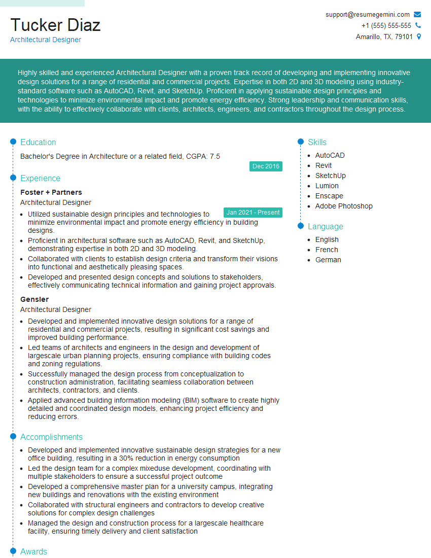
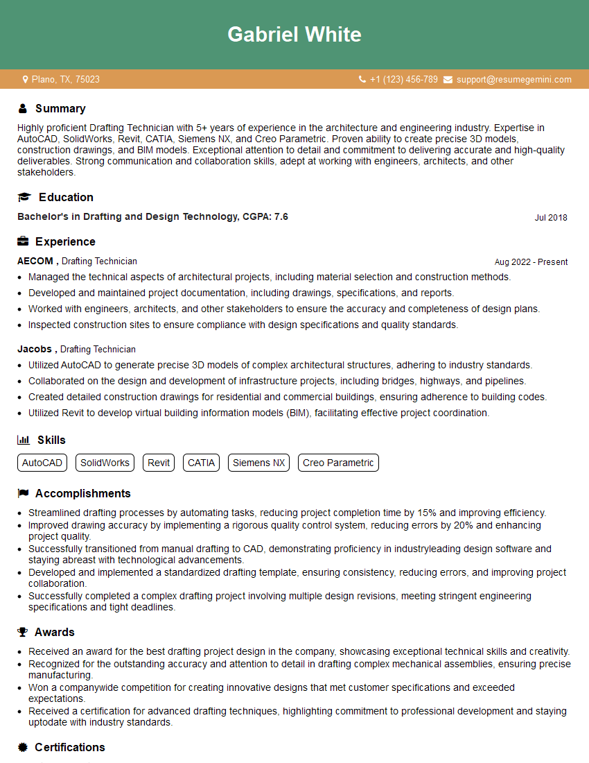
Mastering SolidWorks and AutoCAD opens doors to exciting opportunities in engineering, design, and manufacturing. These skills are highly sought after, leading to rewarding careers and significant professional growth. To maximize your job prospects, it’s crucial to present your skills effectively. Creating an ATS-friendly resume is essential for getting your application noticed by recruiters. We highly recommend using ResumeGemini to build a professional and impactful resume that highlights your expertise in SolidWorks and AutoCAD. ResumeGemini provides examples of resumes tailored specifically to these skills, helping you craft a compelling application that stands out from the competition.
Explore more articles
Users Rating of Our Blogs
Share Your Experience
We value your feedback! Please rate our content and share your thoughts (optional).
What Readers Say About Our Blog
Interesting Article, I liked the depth of knowledge you’ve shared.
Helpful, thanks for sharing.
Hi, I represent a social media marketing agency and liked your blog
Hi, I represent an SEO company that specialises in getting you AI citations and higher rankings on Google. I’d like to offer you a 100% free SEO audit for your website. Would you be interested?


