Every successful interview starts with knowing what to expect. In this blog, we’ll take you through the top Architectural Plans Reading interview questions, breaking them down with expert tips to help you deliver impactful answers. Step into your next interview fully prepared and ready to succeed.
Questions Asked in Architectural Plans Reading Interview
Q 1. What are the standard line types and weights used in architectural drawings?
Architectural drawings employ a standardized system of line types and weights to convey different information at a glance. Think of it like a visual code. Heavier lines represent more prominent features, while lighter lines indicate less significant details. The most common types include:
- Thick, solid lines (heavy weight): These usually define the exterior walls of a building or significant structural elements.
- Medium, solid lines (medium weight): Often used for interior walls, doors, and windows.
- Thin, solid lines (light weight): Represent details like dimensions, notes, and less significant elements.
- Dashed lines: Indicate hidden or concealed features, such as walls behind another wall or plumbing lines.
- Center lines: Thin, long and short dashed lines that show the center of symmetrical elements like columns or rooms. They are crucial for alignment.
- Dimension lines: Thin lines with arrowheads at each end, used to indicate measurements.
- Section lines (hatching): Used to indicate the cut surfaces in sectional drawings, often at a 45-degree angle.
The exact weights might vary slightly depending on the drafting standards used (e.g., ANSI, ISO), but the principle of using varying line weights to distinguish elements remains consistent. For instance, a heavy line defining an exterior wall is immediately visually distinct from a thin line indicating a dimension.
Q 2. Explain the difference between floor plans, elevations, and sections.
Floor plans, elevations, and sections are different views of a building, each offering unique information. Imagine you’re building a house with LEGOs:
- Floor Plans: These are like looking down on your LEGO house from directly above. They show the layout of rooms, walls, doors, windows, and fixtures at a specific level (e.g., ground floor, second floor). You see the horizontal arrangement, the relationship between spaces.
- Elevations: These are like taking pictures of your LEGO house from different sides (front, back, left, right). They show the exterior walls, windows, doors, and roofing, presenting the building’s vertical appearance from a specific viewpoint. You see the heights and vertical relationships.
- Sections: These are like cutting your LEGO house with a knife, showing the internal structure at the cut. Sections illustrate interior wall heights, ceiling heights, the arrangement of floor levels and other interior components along the plane of the cut. You see what’s inside and how high things are.
Each view complements the others. A floor plan shows room sizes, but an elevation shows the exterior detailing of a wall. A section reveals wall constructions and heights, details unseen in a floor plan. A complete set of architectural drawings requires all three to provide a comprehensive understanding of the building’s design.
Q 3. How do you identify north direction on architectural plans?
The north direction is typically indicated on architectural plans using a symbol – usually a half-arrow or a full arrow pointing north with the letter ‘N’. This is crucial for orientation and understanding the building’s relationship to the sun and prevailing winds. The symbol is usually located in a clear area of the drawing, often in a title block or a corner. Its placement needs to be consistent throughout the drawings of a project.
Imagine you’re planning a garden; you need to know which direction the sun shines from to determine the best placement for sun-loving plants. Similarly, knowing north helps architects understand sunlight exposure, views, wind patterns for natural ventilation, and the placement of building features according to best practices and regulations.
Q 4. Describe the information conveyed by a typical detail drawing.
Detail drawings provide magnified, enlarged views of specific building elements. Think of them as close-up shots focusing on critical construction details that require precise information. A typical detail drawing might show:
- Construction Methods: How different materials and components connect, such as how a window frame is installed in a wall.
- Material Specifications: Precise dimensions and types of materials used, helping to avoid ambiguity during construction.
- Finishes and Textures: The specific finishes of a surface, such as tile or plaster, with clear visual indicators and specifications.
- Connections: How structural members join, showing details of beams, columns, and foundations.
Details drawings prevent misunderstandings during construction. Without them, builders might have to make assumptions that lead to errors or inconsistencies. They are essential for ensuring that the final product matches the design intent and meets building codes.
Q 5. How do you interpret dimensioning and scaling on architectural plans?
Dimensioning and scaling are essential for understanding the actual sizes of building elements shown in the often-reduced scale of the drawings. Imagine a scale model of a building; it’s smaller than the real thing, but all the proportions are maintained.
- Scaling: Architectural drawings are typically drawn at a reduced scale (e.g., 1:50, 1:100, or 1/4″=1′). This means 1 unit on the drawing represents a larger number of units in real life. The scale is always clearly indicated on the drawing sheets.
- Dimensioning: This involves adding numerical values to the drawings to show the exact distances between points. Dimension lines with arrowheads and numerical values (e.g., ‘5000mm’) indicate the measurements. Dimensioning provides the precise measurements needed for construction.
For example, if the scale is 1:100 and a dimension on the drawing is 10cm, the actual size is 10cm x 100 = 1000cm (or 10m). Interpreting scale and dimensions correctly is crucial for accurate construction; errors in this aspect can be extremely costly.
Q 6. Explain the significance of different symbols and abbreviations used in drawings.
Architectural drawings use a wealth of symbols and abbreviations to convey information concisely and efficiently. Think of them as a shorthand language for architects and construction professionals. Each symbol represents a specific element or feature. Some standard symbols include:
- Doors and Windows: Specific symbols with dimensions indicating type, swing direction, and size.
- Plumbing Fixtures: Symbols for sinks, toilets, bathtubs, showing their placement and connection points.
- Electrical Outlets and Switches: Symbols indicating locations and types of electrical fixtures.
- Material Indications: Abbreviations or symbols representing materials like concrete, brick, wood, or steel.
For example, ‘WC’ might stand for ‘Water Closet’ (toilet), or a specific symbol might indicate a double-hung window. A key or legend is generally provided on the drawing sheets to explain the meaning of all symbols and abbreviations used within that specific set of drawings.
Q 7. How do you identify different building materials indicated on plans?
Different building materials are indicated on plans through a combination of visual cues and annotations. These methods ensure clarity and precision during the construction phase.
- Visual Cues: Different patterns of hatching or cross-hatching are used within sections to represent different materials. For example, concrete might be represented by dense cross-hatching, while wood might have a different, sparser pattern. Material textures can sometimes be visually indicated as well.
- Annotations and Specifications: Text labels and abbreviations explicitly specify the materials. For example, ‘CMU’ for Concrete Masonry Units, ‘GL’ for Glass, or ‘BRICK’ for brickwork. The material schedule, a separate document within the construction documents, provides comprehensive material details.
- Material Legends or Keys: Drawings often include a legend or key that correlates the symbols and hatching patterns with specific materials.
Recognizing these visual and textual cues requires familiarity with common architectural symbols and practices. Misinterpretation of material indications can lead to significant errors and cost overruns during construction. Consistent referencing of material schedules and legends is a critical step in accurately interpreting material selections indicated on architectural plans.
Q 8. Describe how you would identify potential clashes or conflicts in a set of drawings.
Identifying potential clashes in architectural drawings is crucial for preventing costly rework during construction. My approach involves a multi-step process that combines visual inspection with the use of specialized software.
Visual Inspection: I start by meticulously reviewing each drawing sheet, paying close attention to the interplay between different disciplines. For example, I’d compare the architectural plans with MEP (Mechanical, Electrical, and Plumbing) drawings to identify conflicts between ductwork placement and ceiling heights or beam locations and plumbing runs. I’d also cross-reference structural drawings with architectural details to ensure that columns, beams, and walls align correctly.
Software-Assisted Detection: For larger and more complex projects, I utilize Building Information Modeling (BIM) software. BIM software allows for 3D modeling of the building, facilitating the identification of clashes before construction begins. These tools highlight potential overlaps or interferences between elements from different disciplines, providing precise coordinates and visual representations of the conflict.
Coordination Meetings: I believe in collaborative problem-solving. Regularly scheduled coordination meetings with architects, engineers, and contractors are essential. During these meetings, identified clashes are discussed, solutions are brainstormed, and design modifications are agreed upon. This collaborative approach ensures that all stakeholders are aware of potential issues and contribute to resolving them.
For example, I once discovered a clash between a proposed kitchen island and a vent shaft during a visual review of the plans. Early identification allowed us to reposition the island, preventing a significant construction delay and cost overrun.
Q 9. How do you interpret specifications in conjunction with architectural drawings?
Architectural drawings and specifications work hand-in-hand to provide a complete picture of a building’s design. Drawings show the visual representation, while specifications detail the materials, methods, and performance requirements. They should always be interpreted together to prevent misunderstandings and errors.
Cross-Referencing: I always look for cross-references between the drawings and specifications. Drawings often have notes indicating sections or details where more specific information can be found in the specifications. For example, a drawing might show the type of flooring but the specification will detail the exact product, manufacturer, and installation method.
Prioritizing Specifications: In cases of discrepancies between drawings and specifications, specifications generally take precedence. This is because specifications offer more precise information about the building’s components and their performance standards. However, any major discrepancies are flagged and resolved through communication with the project’s design team.
Understanding Symbols and Abbreviations: Both drawings and specifications use specific symbols and abbreviations. Thorough knowledge of these is essential for accurate interpretation. I often refer to industry standards and project-specific legend to ensure proper understanding.
For instance, a drawing might show ‘concrete slab’ but the specification will dictate the precise concrete mix design, thickness, reinforcement, and finishing requirements.
Q 10. What are common errors or inconsistencies you might find in architectural drawings?
Common errors in architectural drawings are a frequent source of problems on construction sites. They range from minor inconsistencies to significant design flaws. I consistently look for:
Dimensioning Errors: Incorrect or missing dimensions are a common issue. This can lead to misinterpretations and incorrect material ordering.
Scale Discrepancies: Inconsistencies in scales across different drawings are another concern, leading to misalignment of elements.
Missing Details: Often, important details like connection methods, finishes, or specific material specifications are omitted, requiring additional clarification.
Conflicting Information: Contradictory information between drawings and specifications, or even within a single drawing, can lead to confusion and mistakes.
Unclear Markings and Annotations: Poorly labelled or unclear annotations can create ambiguity and impede accurate interpretation.
I remember a project where a minor dimension error in the foundation plan was nearly overlooked. Had it gone unnoticed, it would have resulted in significant problems with the structural framing. This highlights the importance of meticulous checking.
Q 11. Explain your process for checking the accuracy and completeness of plans.
Checking the accuracy and completeness of architectural plans is a rigorous process. My workflow includes:
Completeness Check: I start by verifying that all required sheets and drawings are present and accounted for. This involves checking the issue log or project index to ensure nothing is missing.
Cross-Referencing: I cross-reference details between drawings and the specifications document to ensure consistency. A detailed review of each drawing sheet for completeness is vital.
Dimension and Scale Verification: I carefully verify all dimensions and scales for consistency and accuracy throughout all drawing sets. I look for obvious inconsistencies or missing data.
Adherence to Codes and Standards: I check whether the plans comply with relevant building codes, regulations, and industry best practices. This includes verifying compliance with accessibility requirements and fire safety regulations.
Coordination Review: I perform a thorough review of all disciplines’ drawings for clashes and conflicts. This includes architectural, structural, MEP, and landscaping plans.
Think of it like assembling a complex puzzle; each piece needs to fit perfectly with the others, and if one is missing or incorrect, the whole structure is compromised. My aim is to ensure that every aspect of the plan is thoroughly reviewed for accuracy and completeness.
Q 12. How do you use architectural drawings to estimate materials quantities?
Architectural drawings are essential for accurate material quantity estimation. My approach involves a combination of manual calculations and software-based tools:
Manual Take-Offs: For simpler projects, I perform manual take-offs directly from the drawings. This involves carefully measuring lengths, areas, and volumes from the plans, utilizing the drawing scales and annotations.
Software-Based Estimation: For complex projects, I leverage specialized software designed for quantity takeoff. These tools allow for automated calculations based on the digital drawings, reducing the potential for human error and speeding up the process.
Detailed Specifications Review: I review the specifications carefully, ensuring that the correct materials are accounted for. Specifications provide information about material thicknesses, sizes, and required quantities per unit area.
Waste Factor Inclusion: Real-world construction always involves material waste, so I always include a contingency factor (waste factor) in my estimates. This factor accounts for cutting losses, breakage, and other unavoidable waste.
For example, when estimating the quantity of bricks needed for a wall, I would measure the wall’s length and height, adjust for openings, and then use the brick’s dimensions to calculate the total number of bricks, adding a waste factor to account for breakage and unevenness.
Q 13. How familiar are you with different drawing formats (e.g., PDF, DWG, DXF)?
I am proficient in various architectural drawing formats, including PDF, DWG, and DXF. Each format has its own strengths and weaknesses:
PDF (Portable Document Format): PDFs are excellent for sharing and archiving drawings due to their universality and ability to maintain formatting. However, they are not ideal for editing or making design changes.
DWG (Drawing Exchange Format): DWG is the native file format for AutoCAD and is widely used in the industry. DWG files support layers, annotations, and other critical design features and allow for easy modification.
DXF (Drawing Exchange Format): DXF is a more universal format than DWG, allowing better compatibility between different CAD software. However, it may not retain all of the design features of a DWG file.
My familiarity with these formats ensures that I can efficiently work with any project regardless of the format used by the design team. I can convert between formats if necessary, ensuring seamless workflow and communication.
Q 14. How would you use architectural drawings to assist in construction sequencing?
Architectural drawings are instrumental in developing a logical construction sequence. The drawings provide a visual roadmap for the construction process. My approach involves:
Identifying Dependencies: I carefully review the drawings to identify dependencies between different construction phases. For example, the foundation must be completed before the framing can begin, and the framing must be completed before the exterior walls can be erected.
Sequencing Logic: Based on the dependencies, I create a logical sequence of construction activities, incorporating considerations such as access, safety, and material delivery. This sequence is frequently represented visually using a construction schedule or Gantt chart.
Phasing and Staging: For large projects, phasing the construction work helps to manage resources effectively. Architectural drawings highlight different building sections or stages that can be constructed concurrently or sequentially, allowing for better resource allocation.
Coordination with Drawings: The drawings will identify specific construction details and sequences for particular aspects of the building. For example, the drawings might specify the installation sequence for MEP systems or the steps involved in installing a complex architectural feature.
Imagine building with LEGOs; you wouldn’t start assembling the roof before building the walls. Similarly, constructing a building requires a well-defined sequence, and the drawings serve as the guidebook for this process.
Q 15. How do you interpret building codes and regulations from architectural plans?
Interpreting building codes and regulations from architectural plans requires a systematic approach. It’s not just about reading the drawings themselves, but understanding how the design elements translate into compliance with local, state, and national codes. This involves cross-referencing the plans with the relevant code books. For example, the fire rating of a wall (often indicated by a symbol on the drawings) needs to be verified against the required fire rating for that particular wall type and location as specified by the code. Similarly, egress requirements (means of escape in case of fire), accessibility provisions (ADA compliance for example), and structural requirements (load-bearing capacities, etc.) all have to be checked against the relevant building code sections.
My process typically involves:
- Identifying the relevant codes: Determining which codes apply based on the project’s location and building type (residential, commercial, etc.).
- Cross-referencing: Comparing the plan’s specifications (e.g., dimensions, materials, fire ratings) with the corresponding code requirements.
- Flagging discrepancies: Noting any instances where the design appears to violate the code, and documenting these findings clearly.
- Using code interpretation resources: Consulting supplemental guidance, commentaries, and case studies to clarify ambiguous points in the code.
For instance, if a plan shows a stairway with a less than optimal rise-to-run ratio, I would compare it against the relevant code’s stipulations on safe stairway design, potentially highlighting the discrepancy for further review by the architect or engineer.
Career Expert Tips:
- Ace those interviews! Prepare effectively by reviewing the Top 50 Most Common Interview Questions on ResumeGemini.
- Navigate your job search with confidence! Explore a wide range of Career Tips on ResumeGemini. Learn about common challenges and recommendations to overcome them.
- Craft the perfect resume! Master the Art of Resume Writing with ResumeGemini’s guide. Showcase your unique qualifications and achievements effectively.
- Don’t miss out on holiday savings! Build your dream resume with ResumeGemini’s ATS optimized templates.
Q 16. Explain your experience with working with complex or large-scale projects.
I have extensive experience working on complex and large-scale projects, including a recent project involving a multi-building campus development. This project required meticulous coordination of multiple disciplines (structural, mechanical, electrical, plumbing), navigating hundreds of drawings, and ensuring all systems integrated seamlessly. The challenge was not just the sheer scale, but also managing the intricate relationships between various building systems. For instance, ensuring proper clearances between the HVAC ductwork and structural elements required detailed coordination across multiple drawing sets.
My approach involves breaking down large projects into manageable components. This includes creating a detailed work breakdown structure, assigning priorities to different drawing sets based on their criticality (e.g., structural drawings usually take precedence), and employing collaborative tools to facilitate communication between project stakeholders. We used cloud-based document management and version control systems to maintain consistency and efficiency, and regular meetings were held to address any coordination issues promptly.
Q 17. How do you handle ambiguous or incomplete information on drawings?
Handling ambiguous or incomplete information requires a proactive and investigative approach. It’s crucial to avoid making assumptions. My first step is to thoroughly document the discrepancy, identifying exactly what information is missing or unclear. Then, I’ll use multiple avenues to find the missing information.
These strategies include:
- Consulting other drawings: Often, the answer might be found in a related drawing set (e.g., a detail drawing might clarify a general arrangement drawing).
- Contacting the design team: Directly contacting the architect or engineer responsible for the drawings is crucial to clarify any ambiguities.
- Using professional judgment: In situations where a minor detail is unclear and its absence doesn’t compromise safety or compliance, I might use my professional experience to make a reasonable inference, but always noting this in the documentation.
- Employing industry standards: Defaulting to common industry practices or standards when gaps in information exist, but only after documenting this decision-making process.
For instance, if a dimension is missing on a wall section, I’d review similar wall sections for consistency, contact the architect for clarification, and note the resolution in my review report. Transparency is paramount in these situations.
Q 18. Describe your proficiency with CAD software and its use in interpreting drawings.
I’m proficient in various CAD software, including AutoCAD, Revit, and MicroStation. My expertise extends beyond basic navigation; I utilize the software’s tools to analyze drawings effectively. For example, I use Revit’s sectioning tools to visually inspect the relationship between different building elements, and AutoCAD’s measurement tools to verify dimensional accuracy against code requirements. The ability to manipulate and query model information in Revit is particularly crucial in reviewing complex projects.
Beyond standard drawing review, I use these tools to generate reports, create cross-sections, and enhance drawings for improved communication with stakeholders. For example, I can extract relevant data from a Revit model to generate a schedule of door sizes and materials for compliance review against accessibility codes. My proficiency in these tools significantly speeds up the review process and enhances its accuracy.
Q 19. How do you prioritize information when reviewing multiple drawings for a single project?
Prioritizing information when reviewing multiple drawings involves a tiered approach. Safety and compliance always take precedence. This means that structural drawings, fire protection details, and life safety systems are prioritized for review first. These aspects directly relate to the safety of building occupants and have the greatest potential impact.
My workflow prioritizes:
- Safety-critical systems: Structural, fire protection, and life safety drawings are checked first to ensure that the design meets all code requirements and safety standards.
- Building envelope: Exterior wall assemblies are next, focusing on weatherproofing, insulation, and energy efficiency.
- MEP Systems: Mechanical, electrical, and plumbing drawings are reviewed to ensure that the design is functional, efficient, and code-compliant.
- Architectural finishes: Architectural details, finishes, and materials are addressed later. These are less critical for safety but still crucial for overall project success.
I use a checklist and document management system to ensure that all critical aspects are covered and that nothing is overlooked. A systematic approach ensures comprehensive and effective review.
Q 20. Describe your experience with reviewing plans for compliance with building codes.
My experience in reviewing plans for code compliance is extensive. I regularly review plans across various building types and jurisdictions, ensuring compliance with national, state, and local building codes. This involves a detailed understanding of various codes, including the International Building Code (IBC), accessibility standards (ADA), and fire codes (NFPA). I use a meticulous process that leverages both manual review and digital tools for efficient and comprehensive evaluation.
My process involves:
- Code Familiarization: I start by identifying all relevant building codes for the project’s location and building type.
- Systematic Review: I systematically review each drawing set, checking for compliance with specific code sections. This is facilitated through checklists and standardized templates.
- Digital Tools and Software: I leverage CAD software to accurately measure dimensions, generate reports, and extract key information for code compliance verification.
- Documentation and Reporting: I thoroughly document all findings, including any discrepancies or areas of non-compliance, with clear descriptions and recommendations for correction.
For example, I’ve successfully identified and addressed discrepancies in fire-rated wall assemblies, egress path calculations, and accessibility requirements, preventing costly and potentially hazardous construction errors.
Q 21. How do you communicate effectively with architects and engineers using drawings?
Effective communication with architects and engineers using drawings is key. My approach emphasizes clarity, precision, and collaboration. I avoid vague language and employ precise terminology to ensure that my feedback is easily understood. I utilize markups directly on the drawings to pinpoint specific areas of concern, making it easy for the design team to visualize the issues.
My communication strategies include:
- Clear and concise annotations: I use clear and concise language in all written communication. I write detailed and unambiguous markups directly on the plans.
- Visual aids: I supplement written comments with sketches or additional diagrams when necessary to clarify complex points.
- Constructive feedback: I provide constructive criticism, focusing on solutions rather than simply highlighting problems.
- Formal meetings and discussions: I find in-person or virtual meetings effective for discussing complex issues and resolving conflicts.
In practice, this involves using tools like digital markup software to highlight issues, and then clearly explaining those issues in a well-structured report that includes potential solutions. This collaborative approach ensures that the feedback is actionable and fosters a productive design process.
Q 22. Explain your understanding of different construction methods as depicted in drawings.
Architectural drawings depict various construction methods through symbols, details, and sections. Understanding these requires familiarity with common techniques. For instance, a foundation might be shown as a poured concrete slab (indicated by a solid fill pattern and notes), a concrete block foundation (represented by block outlines and dimensions), or even a pile foundation (depicted with lines representing piles and a foundation cap). Similarly, framing methods are illustrated: wood framing shows dimensional lumber, steel framing uses specific steel section designations, and concrete framing might employ detailed reinforcement drawings. Wall construction details—whether brick veneer, stucco, or insulated panels—are shown with cross sections, specifying materials and layers. Roof types, from gable to hip to shed, are represented visually, and their construction details—trusses, rafters, or other structural elements—are shown in separate drawings. Recognizing these visual cues and corresponding notations is key to understanding the intended construction process.
For example, a drawing showing closely spaced parallel lines with a note specifying ‘100mm concrete slab’ clearly indicates a poured concrete slab foundation. In contrast, a drawing depicting stacked rectangular blocks with specified dimensions and labeled ‘CMU’ (Concrete Masonry Unit) depicts a concrete block wall. These visual representations, accompanied by schedules and specifications, paint a complete picture of the construction process.
Q 23. How would you identify potential safety hazards from a review of architectural plans?
Identifying safety hazards from architectural plans requires a thorough review, focusing on potential issues related to structural integrity, fall protection, fire safety, and accessibility.
- Structural Issues: Insufficient support for loads (e.g., inadequate column sizing for a large span), improperly designed connections, and lack of bracing can all lead to collapse risks. I would meticulously check structural calculations and details for compliance with relevant codes.
- Fall Hazards: The absence of adequate guardrails around elevated areas like balconies, roof edges, or open stairwells is a significant safety concern. Similarly, unprotected openings in floors or roofs represent substantial fall hazards. I examine plans for appropriate fall protection measures indicated in the drawings and specifications.
- Fire Safety: I’d look for proper fire-rated materials specified in walls, floors, and around stairwells. I would also verify that sufficient fire exits and escape routes are provided and clearly indicated on the egress plans.
- Accessibility: I’d ensure the building design complies with accessibility standards, such as proper ramp slopes, door clearances, and restroom accessibility. Non-compliance can result in legal issues and safety problems.
By carefully examining each aspect of the plans and cross-referencing them with relevant building codes, I can effectively identify and document potential safety hazards prior to construction.
Q 24. Describe your process for documenting and reporting errors or discrepancies in drawings.
My process for documenting and reporting errors or discrepancies involves a systematic approach to ensure clarity and avoid miscommunication.
- Identify and Document: I meticulously review all drawings, comparing them for consistency and checking against specifications. Any inconsistencies, omissions, or errors are clearly noted directly on the drawings using red pen or digital annotation tools. I use precise descriptions and referencing, like “Drawing A1.2, detail 3.A – missing dimension.”
- Create a Log: A comprehensive log is maintained, listing each error with its location in the drawings, a detailed description of the issue, and suggested corrective measures. The log is structured for easy understanding and reference by the project team.
- Communicate: The documented errors are communicated to the design team through a formal report, including the log and marked-up drawings. The report clearly explains the problems, their potential consequences, and the necessary corrections. The report is professionally formatted and includes visual aids as appropriate.
- Follow-up: I follow up on the reported issues to ensure corrections are implemented and verified. This might involve attending design review meetings or conducting site visits to confirm the changes are correctly incorporated.
This multi-step process ensures a clear and accountable record of all identified errors and their resolution, minimizing the risk of construction problems caused by drawing errors.
Q 25. How do you stay current with the latest standards and best practices in drawing interpretation?
Staying current with the latest standards and best practices is crucial. I utilize several methods:
- Professional Organizations: Active membership in professional organizations like the AIA (American Institute of Architects) and similar bodies provides access to publications, conferences, and continuing education opportunities that keep me updated on the latest codes and technologies.
- Industry Publications and Journals: I regularly read industry publications and journals to stay abreast of emerging trends and innovations in architectural design and construction.
- Online Resources: I utilize online resources, including building code websites and manufacturers’ information, to access the most current standards and product information.
- Workshops and Seminars: Attending workshops and seminars on relevant topics (e.g., BIM, sustainable building practices, and new construction techniques) further enhances my knowledge and keeps my skills sharp.
- Software Updates: Staying current with updates and training on relevant CAD and BIM software is also crucial for ensuring efficient and accurate interpretation of drawings.
This multifaceted approach ensures that I remain proficient in interpreting and applying current building standards and design practices.
Q 26. Explain your experience with using drawings to solve on-site construction problems.
I’ve used drawings extensively to solve on-site construction problems. One example involved a discrepancy between the shop drawings for steel framing and the original architectural plans. On-site, the steel beams were too short to span the required distance, causing a significant delay. By carefully comparing the architectural plans, the structural calculations, and the shop drawings, I pinpointed the error in the shop drawings—an incorrect beam length calculation. I then worked with the steel fabricator and the project manager to expedite the fabrication and delivery of correctly sized beams, minimizing the overall project disruption.
In another instance, during the construction of a complex curtain wall system, discrepancies arose between the placement of components as shown in the architectural drawings and the manufacturer’s installation instructions. Utilizing the drawings as a base, I collaborated with the installers to clarify the inconsistencies. We then developed a revised installation sequence, incorporating both the design intent and the manufacturer’s best practices, ensuring proper installation and avoiding costly mistakes.
These examples highlight the importance of thorough drawing review and interpretation in resolving on-site construction issues. My experience in effectively using drawings to identify, analyze, and solve problems prevents significant project delays and cost overruns.
Q 27. How would you use architectural drawings to prepare a construction schedule?
Architectural drawings are fundamental in preparing a construction schedule. The process begins by breaking down the project into smaller, manageable tasks based on the drawings.
- Task Identification: I systematically review the plans to identify all construction activities, such as foundation work, framing, MEP (Mechanical, Electrical, Plumbing) installations, interior finishes, etc. Each task is clearly defined and assigned a unique identifier.
- Sequencing: The drawings help determine the logical sequence of these tasks. For example, the foundation must be completed before framing can begin. The detailed plans and sections help understand the interdependencies of different trades and tasks.
- Duration Estimation: Based on the scope of each task (as defined from the drawings), I estimate its duration. This requires consideration of factors like the complexity of the work, the quantity of materials, and the available workforce.
- Resource Allocation: The drawings help assess resource requirements for each task, including labor, equipment, and materials. This information informs the scheduling process and ensures the project has the necessary resources at the right time.
- Scheduling Software: The information gathered is then input into a project scheduling software (like MS Project or Primavera P6) to create a visual schedule representing task dependencies, durations, and milestones.
The resulting schedule is a dynamic tool, subject to revision based on site conditions and project updates. However, the initial schedule is largely shaped by the information and the sequence detailed in the architectural drawings.
Q 28. How do you utilize 3D modeling software to interpret and check architectural plans?
3D modeling software, such as Revit or ArchiCAD, significantly enhances the interpretation and checking of architectural plans. I use these tools to:
- Visualization: The 3D model allows for a comprehensive visualization of the design, revealing potential clashes and conflicts that might be overlooked in 2D drawings. For example, I can easily identify conflicts between MEP systems and structural elements.
- Clash Detection: The software performs automated clash detection, identifying where different elements intersect or overlap. This proactive approach prevents costly on-site rework.
- Quantity Takeoff: Accurate quantity takeoffs for materials are generated, improving cost estimation and procurement planning.
- Section and Detail Generation: I can easily generate sections and details from the 3D model, ensuring consistency and accuracy between the different drawing sets. This is especially helpful for checking complex details.
- Coordination: The 3D model serves as a central hub for collaboration among various disciplines (architects, engineers, contractors). This improved coordination reduces errors and streamlines the construction process.
In essence, 3D modeling transforms the static 2D drawings into a dynamic and interactive model, enhancing understanding, promoting collaboration, and ensuring the accuracy and feasibility of the design before construction begins.
Key Topics to Learn for Architectural Plans Reading Interview
- Plan Views: Understanding floor plans, elevations, sections, and details; interpreting symbols, scales, and annotations.
- Drawing Interpretation: Translating 2D drawings into 3D visualizations; identifying spatial relationships and construction sequences.
- Dimensioning and Tolerances: Accurately measuring dimensions and understanding construction tolerances; recognizing potential conflicts or inconsistencies.
- Materials and Specifications: Identifying building materials from plan notations; understanding material properties and their impact on construction.
- Building Codes and Regulations: Recognizing compliance with building codes and regulations within the plans; identifying potential safety hazards or non-compliance issues.
- Structural Elements: Identifying load-bearing walls, foundations, and structural framing systems; understanding the relationship between structural elements and architectural design.
- MEP Systems (Mechanical, Electrical, Plumbing): Interpreting symbols and notations related to HVAC, electrical, and plumbing systems; understanding their integration within the building design.
- Problem Solving and Analysis: Identifying potential construction challenges, conflicts, or ambiguities within the plans; proposing practical solutions and improvements.
- Software Proficiency: Demonstrating familiarity with relevant software used for architectural plan reading (e.g., AutoCAD, Revit).
- Communication Skills: Clearly and concisely explaining complex architectural concepts and details; effectively communicating findings and recommendations.
Next Steps
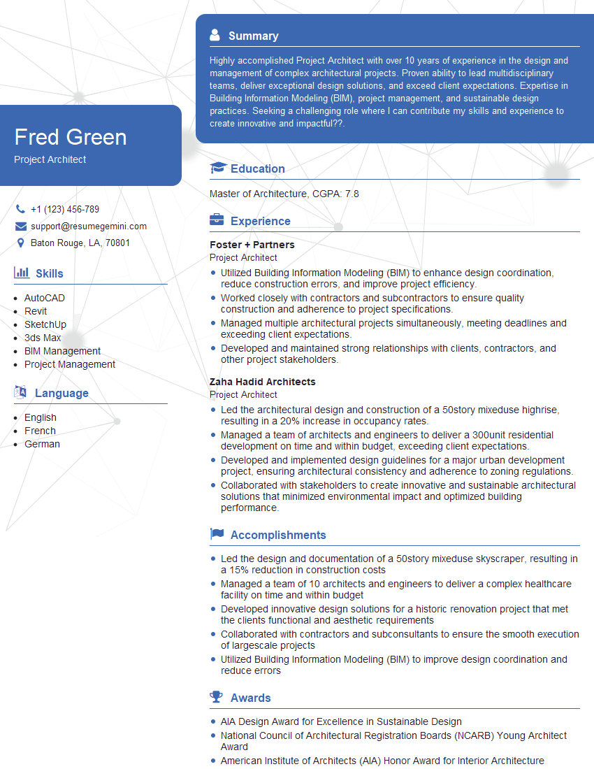
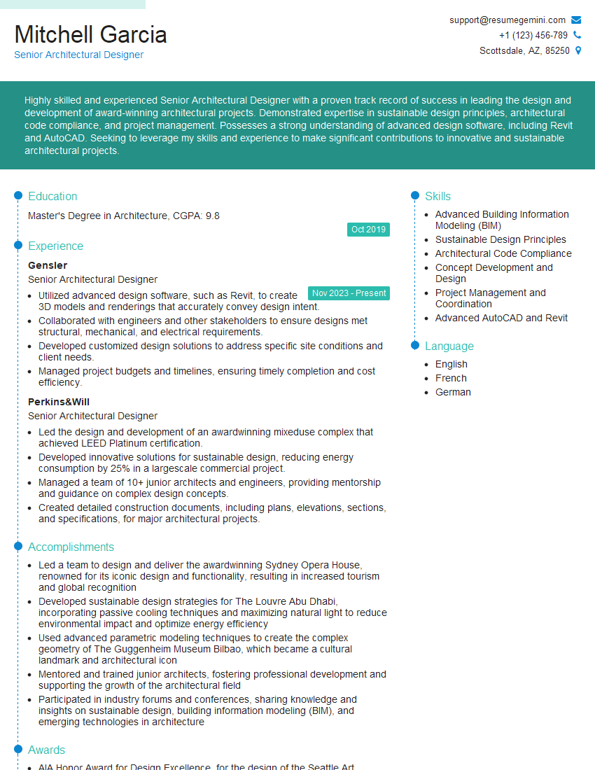
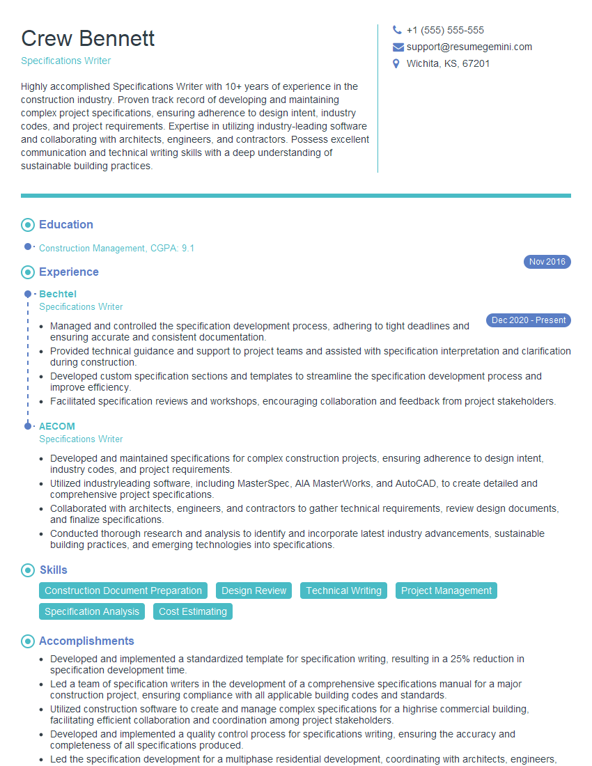
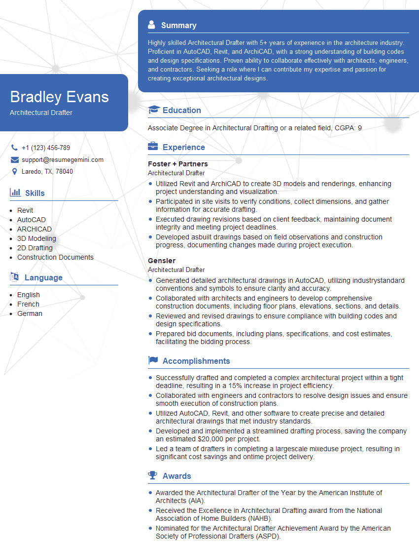
Mastering architectural plans reading is crucial for career advancement in the construction and design industries. It demonstrates essential skills and understanding, opening doors to more challenging and rewarding roles. To maximize your job prospects, create an ATS-friendly resume that highlights your abilities. ResumeGemini is a trusted resource to help you build a professional and impactful resume. They offer examples of resumes tailored specifically for roles requiring architectural plans reading expertise, helping you present your skills effectively to potential employers.
Explore more articles
Users Rating of Our Blogs
Share Your Experience
We value your feedback! Please rate our content and share your thoughts (optional).
What Readers Say About Our Blog
Interesting Article, I liked the depth of knowledge you’ve shared.
Helpful, thanks for sharing.
Hi, I represent a social media marketing agency and liked your blog
Hi, I represent an SEO company that specialises in getting you AI citations and higher rankings on Google. I’d like to offer you a 100% free SEO audit for your website. Would you be interested?
