Interviews are more than just a Q&A session—they’re a chance to prove your worth. This blog dives into essential Beam Flanges interview questions and expert tips to help you align your answers with what hiring managers are looking for. Start preparing to shine!
Questions Asked in Beam Flanges Interview
Q 1. Explain the different types of beam flanges and their applications.
Beam flanges, the horizontal elements of I-beams, T-beams, and other similar sections, come in various types, each suited for specific applications. The choice depends heavily on factors such as load, material, and fabrication methods.
- Rolled Steel Flanges: These are the most common, produced directly from steel mills. Their efficiency stems from optimized geometries and consistent material properties. They’re ideal for standard construction applications, bridges, and many industrial structures.
- Welded Flanges: Created by welding plates together, welded flanges offer greater design flexibility. They allow for custom sizes and shapes not readily available in rolled sections, making them suitable for complex or non-standard projects. Think of specialized machinery supports or unique building designs.
- Cast Flanges: These flanges are cast from molten metal (often steel or iron), allowing for intricate shapes and internal features. They might be chosen for applications needing high corrosion resistance or specific geometric constraints. You could find these in situations needing high dimensional accuracy or unique designs.
- Built-up Flanges: For extremely large or specialized beams, engineers can create built-up flanges by assembling multiple smaller sections. This approach enhances strength and allows for tailoring the flange geometry to suit the load and support requirements. This method is frequently used in very large spans or for bespoke structures.
The choice between these types involves a trade-off between cost, availability, design flexibility, and the structural requirements of the project.
Q 2. Describe the process of selecting the appropriate beam flange for a given application.
Selecting the appropriate beam flange is a crucial step in structural design. It’s a multi-faceted process involving several considerations:
- Load Determination: Accurately determine the loads the beam will carry (dead loads, live loads, wind loads, etc.). This forms the basis of all subsequent calculations.
- Material Selection: Choose a suitable material based on strength, ductility, corrosion resistance, and budget. Common choices include various grades of steel and aluminum alloys.
- Span and Support Conditions: The length of the beam and the type of supports (simply supported, cantilever, etc.) significantly influence the bending moment and shear force diagrams, which guide flange selection.
- Code Compliance: Adhere to relevant building codes and standards (e.g., AISC, Eurocodes) to ensure safety and legal compliance.
- Stress Analysis: Perform detailed stress analysis to ensure the selected flange can withstand the stresses imposed by the loads. This typically involves determining bending stresses, shear stresses, and deflection.
- Deflection Checks: Ensure the chosen beam’s deflection under load is within acceptable limits, considering serviceability criteria. Excessive deflection can affect aesthetics and functionality.
- Buckling Considerations: Assess the risk of flange buckling, especially under compressive loads. This often involves checking slenderness ratios and applying appropriate buckling factors.
- Cost Optimization: Select the most economical beam flange that meets all design requirements. This often involves comparing different section sizes and materials.
Software tools are often employed to facilitate the analysis and selection process. These tools automate calculations and allow for rapid iteration through different design options.
Q 3. How do you calculate the shear capacity of a beam flange?
The shear capacity of a beam flange is its resistance to shear stresses. It’s calculated by considering the flange’s area and the allowable shear stress of the material.
For a rectangular flange:
Shear Capacity = Allowable Shear Stress * Area of FlangeWhere:
- Allowable Shear Stress: This value is obtained from material specifications and accounts for safety factors.
- Area of Flange: This is simply the cross-sectional area of the flange (width x thickness).
For more complex flange geometries, more sophisticated analysis techniques might be required, potentially involving Finite Element Analysis (FEA).
Example: Let’s say the allowable shear stress of a steel flange is 150 MPa, and the flange has dimensions of 100 mm x 20 mm. The shear capacity would be:
Shear Capacity = 150 MPa * (100 mm * 20 mm) = 300,000 NIt’s crucial to remember that this is a simplified calculation. The actual shear capacity can be influenced by factors such as stress concentrations, weld details, and other design features.
Q 4. How do you calculate the bending moment capacity of a beam flange?
The bending moment capacity of a beam flange is its resistance to bending stresses. The calculation involves the section modulus of the beam section and the allowable bending stress of the material.
The bending moment capacity (Mb) is given by:
Mb = Allowable Bending Stress * Section Modulus (S)Where:
- Allowable Bending Stress: This value is obtained from material specifications and considers safety factors. It’s often different from the yield stress of the material to incorporate a safety margin.
- Section Modulus (S): This geometric property represents the beam’s resistance to bending. It’s calculated based on the cross-sectional shape of the beam, including the flange’s dimensions. For a rectangular section, S = (b*d^2)/6 where b is width and d is depth. Standard steel sections have readily available section moduli in engineering handbooks and structural steel manuals.
Example: Suppose a steel I-beam has a section modulus of 1000 cm3 and an allowable bending stress of 250 MPa. Its bending moment capacity would be:
Mb = 250 MPa * 1000 cm3 = 250,000,000 N·cm = 2,500,000 N·mAccurate calculation of the section modulus is vital; using the wrong value can lead to significant errors in design.
Q 5. Explain the concept of flange buckling and how to prevent it.
Flange buckling occurs when a compressed flange (often under bending loads) buckles laterally, compromising the beam’s structural integrity. It’s similar to how a thin, unsupported ruler bends when pressure is applied to its ends.
Several factors influence flange buckling:
- Flange slenderness: A slender flange (high width-to-thickness ratio) is more prone to buckling.
- Unsupported length: A longer unsupported flange length increases the risk of buckling.
- Compressive stress: Higher compressive stresses in the flange increase the likelihood of buckling.
- Material properties: The material’s elastic modulus and yield strength affect buckling resistance.
Preventing flange buckling can be achieved through:
- Stiffeners: Adding stiffeners (vertical or horizontal plates welded to the flange) increases its resistance to lateral buckling.
- Increased thickness: Using thicker flanges reduces the slenderness ratio and increases resistance to buckling.
- Lateral bracing: Providing lateral support to the flanges, such as using bracing members, can prevent buckling.
- Optimizing flange geometry: Designing flanges with appropriate width-to-thickness ratios can mitigate buckling risks.
Structural analysis software helps predict the likelihood of buckling and guide the selection of appropriate preventative measures. The design needs to ensure the flange’s buckling capacity exceeds the anticipated stresses.
Q 6. Describe different types of beam flange connections (e.g., welds, bolts).
Beam flange connections are crucial for transferring loads efficiently and safely. Various methods exist, each with advantages and limitations.
- Welding: Welding provides a strong and continuous connection, ideal for transferring both shear and moment. Different weld types (e.g., fillet welds, butt welds) are chosen based on strength and accessibility requirements. Welding is often preferred for its strength and efficiency in transferring loads, particularly in high-stress applications.
- Bolting: Bolting offers a more flexible connection, enabling easy assembly and disassembly. Bolted connections often involve high-strength bolts and properly designed connection plates to ensure sufficient shear and moment resistance. Bolting is more suitable for situations where dismantling or maintenance is anticipated.
- Riveting (less common now): Rivets were traditionally used for creating strong connections, though welding and high-strength bolting have largely replaced them in modern construction.
The choice depends on several factors, including the load magnitude, the desired level of stiffness, fabrication ease, maintenance requirements, and cost considerations.
Q 7. How do you design a beam flange connection to resist shear and moment?
Designing a beam flange connection to resist shear and moment requires careful consideration of several aspects.
- Load Calculation: Accurately determine the shear forces and bending moments acting on the connection based on structural analysis. This will define the forces your connection needs to handle.
- Connection Type Selection: Select the most suitable connection type (welded or bolted) based on the factors mentioned in the previous answer. This selection needs to consider the load levels and ease of fabrication.
- Connection Detailing: Design the connection details meticulously, specifying the size, type, and spacing of welds or bolts. The detailing phase is crucial for guaranteeing the strength and integrity of the connection.
- Strength Verification: Verify the connection’s strength under the calculated loads. This involves checking the capacity of the welds or bolts in shear, bearing, and tension. This includes accounting for the capacity of the connected elements.
- Fatigue Considerations: If the connection is subjected to cyclic loading, fatigue analysis is necessary to ensure it won’t fail prematurely due to fatigue. Cyclic loads need particular attention because they can cause premature failure.
- Ductility and toughness: Consider using materials that demonstrate high ductility and toughness, which help to prevent brittle failure under overload conditions.
- Code Compliance: Ensure that the design adheres to relevant building codes and standards for connection details and weld/bolt capacities. The design must be compliant with the applicable codes to guarantee its safety and legality.
Engineering software packages, combined with relevant design codes and standards, are invaluable tools in ensuring a safe and efficient beam flange connection design.
Q 8. Explain the importance of weld size and type in beam flange connections.
The weld size and type in beam flange connections are crucial for ensuring the structural integrity and load-bearing capacity of the entire structure. An improperly sized or typed weld can lead to premature failure. The weld needs to be strong enough to transfer the loads from the beam flange to the connected member without yielding or fracturing.
Weld Size: The weld size is directly related to the strength of the connection. A larger weld size provides greater shear and tensile capacity. The size is dictated by the applied loads, the thickness of the connected members, and relevant design codes. Insufficient weld size results in a weak connection prone to failure under load. We select weld size based on the design load and the allowable stress of the weld material according to applicable codes like AWS D1.1.
Weld Type: Different weld types offer varying strengths and resistances to different types of stress. For example, a fillet weld is commonly used for beam flange connections, providing shear strength. A full penetration groove weld offers superior strength but is more complex and expensive to execute. The choice of weld type depends on the specific application, the geometry of the connected members, and the required strength. A butt weld, for instance, is stronger in tension than a fillet weld.
Example: Imagine connecting a wide flange beam to a column. A small fillet weld might fail under heavy loading. A larger fillet weld or a groove weld, designed according to the applicable standards, will ensure a safe and durable connection.
Q 9. How do you account for fatigue effects in beam flange design?
Fatigue effects are accounted for in beam flange design by considering the cyclic loading the connection might experience. Fatigue failure occurs when a component is subjected to repeated cycles of stress, even if the stress level is below the ultimate tensile strength. Over time, micro-cracks form and propagate, eventually leading to failure.
Methods for Accounting for Fatigue:
- Stress Range: The design must consider the range of stress variation during cyclic loading. We calculate the maximum and minimum stresses in the weld and the flange.
- Fatigue Life Calculations: We use fatigue analysis software or equations (like the S-N curve) to determine the number of cycles a connection can withstand before fatigue failure. These curves correlate the applied stress range to the number of cycles to failure.
- Fatigue Details: Designing for fatigue often involves incorporating features such as generous radii at stress concentration points (like weld toes) to reduce stress concentrations and improve fatigue life. Proper weld preparation and finishing techniques are also essential.
- Material Selection: Using high-strength, fatigue-resistant materials (like high-strength steel) improves fatigue performance.
Example: A bridge subjected to repeated truck loads requires detailed fatigue analysis of all welds. The design will need to account for the expected number of load cycles over the bridge’s design life.
Q 10. What are the common failure modes of beam flanges?
Beam flanges can fail in several ways, mainly depending on the loading and design conditions:
- Yielding: Excessive stress exceeding the yield strength of the flange material can cause plastic deformation and loss of structural integrity. This often manifests as bending or buckling.
- Fracture: Brittle fracture can occur due to high stress concentrations or flaws in the material, leading to sudden catastrophic failure. This is often associated with low temperatures or material defects.
- Buckling: Slender flanges can buckle under compressive loads, losing their load-carrying capacity. This depends on the flange’s geometry, material properties, and support conditions.
- Weld Failure: Weld failures can occur due to poor weld quality, inadequate weld size, or fatigue. Failure can be in the form of shear, tension, or fatigue cracking.
- Lateral-Torsional Buckling: The entire beam, including the flange, can experience lateral-torsional buckling, a complex failure mode under bending loads. This is influenced by the beam’s overall geometry and the presence of lateral supports.
Understanding these failure modes is critical in designing safe and reliable beam flange connections.
Q 11. How do you account for corrosion in the design of beam flanges?
Corrosion significantly reduces the load-bearing capacity of beam flanges. It is crucial to account for corrosion effects in the design to ensure the structure’s longevity and safety.
Methods to Account for Corrosion:
- Corrosion Allowance: Increasing the thickness of the beam flange to compensate for the expected corrosion loss over the structure’s design life. This is a common approach, especially for outdoor structures exposed to harsh environments.
- Protective Coatings: Applying coatings such as paint, galvanization, or other corrosion-resistant materials to the flanges. The choice of coating depends on the environment and the required level of protection.
- Material Selection: Using corrosion-resistant materials such as stainless steel or weathering steel can reduce or eliminate the need for additional corrosion protection.
- Corrosion Inhibitors: Employing corrosion inhibitors, such as chemical treatments, can slow down the corrosion process.
- Regular Inspection and Maintenance: Implementing a regular inspection and maintenance program to detect and address corrosion issues promptly. This allows timely intervention to prevent widespread damage.
The design should consider the expected corrosion rate, the material’s corrosion resistance, and the environment’s aggressiveness when selecting the appropriate corrosion mitigation measures.
Q 12. Explain the role of detailing in ensuring proper beam flange installation.
Detailing plays a vital role in ensuring proper beam flange installation by providing clear and unambiguous instructions for fabricators and erectors. Accurate detailing minimizes errors and ensures the connection behaves as intended.
Importance of Detailing:
- Weld Dimensions and Location: Detailed drawings must specify the weld size, type, length, and location precisely. This ensures the correct amount of weld is applied in the right place.
- Bolt Specifications: If bolts are used, the detailing should specify the bolt size, type, grade, and spacing to ensure a secure connection.
- Material Specifications: The type and grade of steel used for the beam flange and the connected members must be clearly identified.
- Tolerances: Acceptable fabrication tolerances should be specified to prevent installation problems. The drawings should clearly indicate allowable variations in dimensions and welding.
- Clear Markings: Drawings should include clear markings to help identify components and ensure correct assembly during fabrication and erection.
Well-prepared detailing minimizes ambiguity and reduces the chances of installation errors, leading to a safer and more reliable structure.
Q 13. How do you inspect beam flanges for defects?
Inspection of beam flanges for defects involves a multi-stage process, combining visual inspection with advanced techniques. The goals are to detect any flaws that compromise the structural integrity before, during and after installation.
Inspection Methods:
- Visual Inspection: A thorough visual examination for surface cracks, corrosion, deformation, or other visible defects. This is a basic yet important first step.
- Ultrasonic Testing (UT): UT uses high-frequency sound waves to detect internal flaws such as cracks, voids, or inclusions. It’s excellent for finding hidden defects.
- Magnetic Particle Inspection (MPI): MPI uses magnetic fields to detect surface and near-surface cracks in ferromagnetic materials. It is effective in finding cracks associated with welding.
- Dye Penetrant Inspection (DPI): DPI is used to detect surface-breaking flaws by applying a dye that penetrates the crack and is then revealed by a developer. It’s suitable for detecting smaller surface cracks.
- Radiographic Testing (RT): RT uses X-rays or gamma rays to create images of internal structures, revealing internal defects like porosity or cracks. It provides a detailed view of the internal structure.
The selection of inspection methods depends on the severity of the application, the size and location of the welds, and the materials used.
Q 14. What are the common codes and standards used in beam flange design?
Several codes and standards govern the design of beam flanges, ensuring structural safety and consistency. The specific codes used depend on the location, application, and material used in the structure.
Common Codes and Standards:
- AISC (American Institute of Steel Construction): AISC provides specifications and design guides for steel structures, including beam design and connections. Their Steel Construction Manual is a widely used reference.
- ASCE (American Society of Civil Engineers): ASCE publishes standards and guidelines for various aspects of civil engineering, including structural design and analysis.
- AWS (American Welding Society): AWS provides standards for welding procedures, qualifications, and inspection, essential for ensuring proper execution of beam flange welds.
- Eurocodes (EN): The Eurocodes are a set of harmonized standards for structural design used in Europe. EN 1993-1-1 deals specifically with the design of steel structures.
- National Building Codes: Many countries have their own national building codes that incorporate or reference international standards, providing specific design requirements and regulations.
It’s crucial to adhere to the relevant codes and standards throughout the design, fabrication, and inspection process to ensure structural integrity and compliance.
Q 15. Explain the difference between hot-rolled and cold-formed beam flanges.
The key difference between hot-rolled and cold-formed beam flanges lies in their manufacturing process. Hot-rolled flanges are formed from a heated steel billet that is passed through a series of rollers, shaping it into the desired profile. This process allows for the creation of larger and thicker sections. In contrast, cold-formed flanges are manufactured from pre-rolled steel sheets or coils at room temperature, often employing processes like bending, pressing, or rolling to achieve the final shape. Cold forming allows for more precise shapes and tighter tolerances, typically resulting in lighter sections, but these are usually thinner and more susceptible to buckling.
Think of it like this: hot rolling is like sculpting with clay; you start with a large lump and shape it roughly. Cold forming is like sculpting with a precision carving tool, resulting in more intricate detail but requiring careful attention.
- Hot-rolled: Larger sections, thicker material, higher yield strength, less precise tolerances, cost-effective for larger projects.
- Cold-formed: Lighter sections, thinner material, higher precision, potential for tighter tolerances, suitable for lighter-duty applications and prefabricated components.
Career Expert Tips:
- Ace those interviews! Prepare effectively by reviewing the Top 50 Most Common Interview Questions on ResumeGemini.
- Navigate your job search with confidence! Explore a wide range of Career Tips on ResumeGemini. Learn about common challenges and recommendations to overcome them.
- Craft the perfect resume! Master the Art of Resume Writing with ResumeGemini’s guide. Showcase your unique qualifications and achievements effectively.
- Don’t miss out on holiday savings! Build your dream resume with ResumeGemini’s ATS optimized templates.
Q 16. How do you determine the required section modulus of a beam flange?
Determining the required section modulus of a beam flange involves considering the bending moment the flange will experience and the allowable bending stress of the material. The section modulus (S) is a geometric property that relates the bending moment (M) to the bending stress (σ) using the formula: σ = M/S.
Therefore, to find the required section modulus, you need to first determine the maximum bending moment acting on the beam. This can be done using structural analysis techniques, considering the load and support conditions. Then, using the allowable bending stress (which is determined from the material’s properties and relevant design codes), you can calculate the required section modulus: S = M/σ. For example, if the maximum bending moment is 100 kN-m and the allowable stress is 250 MPa, the required section modulus would be S = 100,000 Nm / 250 x 10^6 N/m² = 4 x 10^-4 m³. Always check the relevant design codes for specific requirements and safety factors.
Q 17. Describe the process of analyzing beam flange stresses using FEA.
Finite Element Analysis (FEA) provides a powerful tool for analyzing stresses in beam flanges under complex loading conditions. The process involves creating a detailed computer model of the beam flange, defining its material properties, and applying the anticipated loads. The FEA software then divides the model into numerous smaller elements, solving equations for each element to determine the stress and strain distributions throughout the flange.
Specifically, you would:
- Create a 3D model: Accurately representing the geometry of the flange, including any welds or holes.
- Define material properties: Inputting the Young’s modulus, Poisson’s ratio, and yield strength of the chosen steel.
- Apply boundary conditions: Simulating the supports and restraints of the beam.
- Apply loads: Specifying the magnitude, direction, and location of the forces acting on the flange (dead load, live load, wind load, seismic load, etc.).
- Mesh the model: Dividing the model into a fine mesh of elements for accurate stress calculation.
- Solve the analysis: The FEA software performs the calculations and produces results that display stress distributions visually (e.g., contour plots).
- Review and interpret results: Examine the maximum stress values and locations to ensure they are within acceptable limits.
FEA allows for detailed stress analysis in areas of stress concentration, such as fillet welds or corners, providing valuable information for refined design and optimization.
Q 18. How do you account for the effect of web crippling in beam flange design?
Web crippling is the localized failure of a beam’s web near a concentrated load, which can affect the flange’s performance. To account for this, designers use several approaches:
- Increased Web Thickness: A thicker web resists crippling more effectively. This is a straightforward solution, especially for beams carrying significant concentrated loads.
- Stiffeners: Adding stiffeners, such as plates or angles, to the web around the concentrated load increases the web’s resistance to buckling and improves its load-carrying capacity.
- Design Codes and Provisions: Design codes (e.g., AISC, Eurocode) provide specific equations and procedures to assess web crippling. These provisions consider the load, web geometry, and material properties to determine the allowable concentrated load.
- FEA Analysis: FEA can provide detailed stress and displacement analysis near the concentrated load, allowing verification that the web’s performance is satisfactory.
Proper consideration of web crippling is critical, as neglecting it can result in premature failure of the beam. The choice of approach depends on the specific loading condition, the beam geometry, and the construction method.
Q 19. What are the advantages and disadvantages of using different types of steel for beam flanges?
Various steel grades can be used for beam flanges, each with its own advantages and disadvantages:
- High-strength steels: (e.g., ASTM A992, A572) Offer higher yield strength, allowing for lighter sections and reduced material costs. However, they may be more expensive and require more careful welding considerations.
- Mild steels: (e.g., ASTM A36) Lower yield strength, resulting in heavier sections, but they are more readily available and easier to weld. This also means they can be better suited to welding environments in the field.
- Weathering steels (COR-TEN): Develop a protective oxide layer, reducing the need for painting and maintenance. But initial cost may be higher, and design considerations need to account for the slightly lower strength.
The optimal steel type depends on the project’s specific requirements, including cost, strength, durability, welding considerations, and environmental factors. For example, a high-rise building might justify the cost of high-strength steel for lighter weight, while a simple farm structure might opt for readily available mild steel for economy.
Q 20. Explain how to design beam flanges for seismic loading.
Designing beam flanges for seismic loading requires careful consideration of the potential forces and displacements during an earthquake. Key factors include:
- Seismic Codes and Standards: Adherence to relevant seismic design codes (e.g., ASCE 7, IBC) is crucial. These codes specify design requirements, load combinations, and analysis methods.
- Ductility: Designing for sufficient ductility allows the beam to withstand significant deformations without brittle fracture. This often involves selecting appropriate materials and detailing to promote ductile behavior.
- Shear Capacity: Adequate shear capacity is essential to prevent shear failure during seismic events. This is closely tied to the web design, often needing checks for shear buckling.
- Moment Capacity: Sufficient moment capacity is necessary to resist the bending moments induced by seismic loading. This determines the flange’s size and material.
- Connection Design: Strong and ductile connections are critical to transfer seismic forces efficiently. The design and detail of the connections between the beam flanges and the supporting columns are paramount.
- Dynamic Analysis: For complex structures or high seismic zones, dynamic analysis (e.g., time-history analysis) may be required to accurately simulate the seismic response of the beam.
Seismic design is a complex area, and collaboration with experienced structural engineers is essential to ensure safety and compliance with codes.
Q 21. How do you ensure proper alignment and fit-up of beam flanges during construction?
Ensuring proper alignment and fit-up of beam flanges during construction is essential for the structural integrity of the entire assembly. Key steps include:
- Accurate Fabrication: Precise fabrication of the beam flanges themselves is the first critical step. This often uses computer-aided manufacturing techniques for maximum precision.
- Proper Erection Planning: A detailed plan for beam placement and alignment should be developed before construction begins, considering factors like access, lifting equipment, and temporary supports.
- Use of Templates and Jigs: Templates and jigs can be used during construction to accurately position and align the beam flanges, minimizing errors.
- Accurate Measurements and Surveys: Regular measurements and surveys should be carried out to verify alignment throughout the construction process.
- Specialized Lifting Equipment: Utilizing appropriate lifting equipment, including specialized slings and rigging, is crucial to avoid damage and maintain precise alignment.
- Welding and Bolting Procedures: Precise welding and bolting procedures should be followed to ensure the connections are strong and maintain accurate alignment.
- Quality Control Inspection: Regular inspections by qualified personnel throughout the construction process are necessary to identify and correct any misalignment problems early.
Neglecting proper alignment and fit-up can result in significant stresses in the beam and its connections, reducing structural integrity and safety. A careful and meticulous approach is vital throughout the entire construction process.
Q 22. What are the common quality control checks for beam flanges?
Quality control for beam flanges is crucial for structural integrity and safety. It involves a multi-stage process encompassing material testing, dimensional checks, and weld inspection.
- Material Testing: This includes verifying the chemical composition and mechanical properties (yield strength, tensile strength, etc.) of the steel used, often using tensile testing and chemical analysis. This ensures the material meets the specified grade and standards.
- Dimensional Checks: Precise measurements are taken to ensure the flange dimensions (thickness, width, length) conform to the design specifications. This includes verifying the flange angles and straightness. Deviations can significantly impact the structural performance.
- Weld Inspection: For welded connections, rigorous inspection is vital. This typically involves visual inspection, followed by non-destructive testing (NDT) methods such as radiographic testing (RT), ultrasonic testing (UT), or magnetic particle testing (MT) to detect internal flaws like porosity or cracks in the weld. The quality of welds directly impacts the load-bearing capacity of the connection.
- Geometric Checks: Verification of the overall geometry of the fabricated flange against the design drawings ensures correct alignment and prevents any potential structural problems
Imagine building a house – you wouldn’t use substandard bricks or improperly laid mortar. Similarly, compromised beam flanges due to poor quality control can lead to catastrophic failure.
Q 23. How do you deal with beam flange deflection issues?
Beam flange deflection issues arise when the flange bends excessively under load, exceeding allowable limits. Addressing this involves a multifaceted approach.
- Strengthening: This could involve increasing the flange thickness, adding stiffeners (e.g., additional plates welded to the flange), or using a stronger grade of steel. The choice depends on the severity of the deflection and the constraints of the project.
- Support Modification: Insufficient or improperly placed supports can contribute to deflection. Adding supports or re-positioning existing ones can dramatically reduce the bending moment and therefore the deflection. For instance, adding intermediate supports to a long span beam can significantly improve performance.
- Redesign: In severe cases, a complete redesign might be necessary. This involves recalculating the section properties and selecting a more appropriate beam section with a greater moment of inertia to resist bending.
- Load Redistribution: If the excessive load is the root cause, redistributing the load or reducing the applied loads can mitigate the deflection. This might involve structural changes or operational adjustments.
For example, if a floor beam is deflecting excessively, we might add additional supports to the floor system, increasing the number of load-bearing points.
Q 24. Explain the concept of plastic hinge formation in beam flanges.
Plastic hinge formation in beam flanges is a concept related to structural mechanics where a localized region of the flange undergoes significant yielding and large deformations under high loads.
Imagine bending a metal coat hanger – it doesn’t break immediately. Instead, it bends significantly at a specific point before finally breaking. This point of significant bending is analogous to a plastic hinge. In a beam flange, this yielding occurs when the bending moment exceeds the plastic moment capacity of the section. Once a plastic hinge forms, the section loses its stiffness and rotational capacity, leading to increased deflections and potentially collapse.
The formation of plastic hinges is accounted for in limit state design methods, which allow for some plastic deformation before failure. Design codes often provide criteria for checking against plastic hinge formation and ensuring sufficient ductility to prevent brittle fracture.
Q 25. How do you address potential weld defects in beam flange connections?
Weld defects in beam flange connections can severely compromise the structural integrity and must be addressed promptly and effectively.
- Defect Identification: This initially involves visual inspection, followed by NDT methods such as radiography (RT), ultrasonic testing (UT), or magnetic particle inspection (MPI) to detect and characterize the defects (e.g., cracks, porosity, lack of fusion).
- Defect Classification: The severity of the defect is classified based on its size, location, and type, following relevant welding codes (e.g., AWS D1.1). This determines the necessary corrective action.
- Repair or Replacement: Minor defects may be repaired by grinding and re-welding, whereas significant defects necessitate the replacement of the entire welded component. The repair procedure must be carefully planned and executed to restore the structural integrity.
- Documentation: Thorough documentation of the defect, the inspection procedures, and the repair or replacement is essential for traceability and quality assurance.
Ignoring weld defects can lead to premature failure, posing safety risks. Proper inspection and remediation are critical.
Q 26. Describe your experience with different types of beam flange detailing software.
Throughout my career, I’ve extensively used various beam flange detailing software packages. My experience includes:
- Tekla Structures: A powerful 3D BIM modeling software capable of creating detailed models of beam flanges and connections, including weld simulations and clash detection. I’ve used it on large-scale projects to efficiently design and detail complex steel structures.
- Autodesk Robot Structural Analysis: This software enables comprehensive structural analysis of beam flanges, allowing for the verification of stresses, deflections, and buckling. I’ve leveraged this for optimization studies and to ensure designs meet stringent code requirements.
- Advance Steel: This software is specifically geared towards steel detailing. I’ve used it to create detailed fabrication drawings, including shop drawings for beam flanges and connections, enhancing communication between design and fabrication teams.
Each software has its strengths and weaknesses, and the choice depends on the project’s complexity and the specific needs of the design team. Proficiency in multiple software packages provides a wider range of solutions for different project demands.
Q 27. How do you interpret and apply design codes for beam flange design?
Interpreting and applying design codes for beam flange design is fundamental to ensuring structural safety and compliance. My approach follows a systematic process.
- Code Selection: The relevant design code is identified based on the project’s location and the applicable building codes (e.g., AISC 360 in the US, Eurocode 3 in Europe). Understanding the specific requirements of the selected code is crucial.
- Load Determination: Accurate determination of all applied loads (dead loads, live loads, wind loads, seismic loads) is essential. This includes considering load combinations and factors of safety as per the code.
- Section Selection: Based on the determined loads and the code requirements, appropriate beam sections are chosen to ensure adequate strength and stiffness. This involves checking for bending, shear, and deflection limits.
- Connection Design: The design of the beam flange connections (e.g., welds, bolts) is a critical step, ensuring they meet the code’s requirements for strength and ductility. This typically involves weld size calculations and bolt strength checks.
- Verification: The design is verified using appropriate analytical methods (e.g., hand calculations, FEA) to confirm that all code requirements are met.
Design codes aren’t rigid rules but guidelines that must be thoroughly understood and intelligently applied to guarantee a safe and functional structure.
Q 28. Explain your experience with troubleshooting beam flange related problems on a project.
On a recent high-rise project, we encountered unexpected deflection in some secondary beam flanges.
The initial investigation revealed that the design calculations had underestimated the live load due to a misinterpretation of the occupancy loads. We utilized finite element analysis (FEA) to model the structure and pinpoint the areas of highest stress and deflection. This revealed that a significant portion of the live load was being transferred to the secondary beams, exceeding their design capacity.
Our solution involved a two-pronged approach:
- Design Modification: We increased the size of the affected secondary beams to increase their stiffness and moment capacity. This required careful coordination with the construction team to ensure the changes could be implemented without significant delays.
- Load Redistribution: We also re-evaluated the overall structural system to redistribute the loads more efficiently, reducing the load on the secondary beams. This involved adding additional structural members to the primary framing system.
The problem was successfully resolved through meticulous analysis, effective communication with the project stakeholders, and a proactive approach to finding viable solutions. The FEA modeling was particularly helpful in visualizing the stresses and accurately predicting the impact of our proposed solutions.
Key Topics to Learn for Beam Flanges Interview
- Types of Beam Flanges: Understanding the different types (e.g., I-beams, channel beams, T-beams) and their respective applications.
- Material Properties and Selection: Knowledge of relevant materials (steel, aluminum, etc.) and how their properties influence flange design and performance under stress.
- Stress Analysis and Design Calculations: Familiarity with methods for calculating bending stress, shear stress, and deflection in beam flanges, including relevant formulas and software applications.
- Welding and Fabrication Techniques: Understanding common welding methods used in beam flange fabrication and their implications for structural integrity.
- Connection Design and Fasteners: Knowledge of different methods for connecting beam flanges to other structural elements (bolts, welds, etc.) and the associated design considerations.
- Failure Modes and Analysis: Understanding potential failure mechanisms in beam flanges (e.g., buckling, yielding, fatigue) and methods for preventing them.
- Code Compliance and Standards: Familiarity with relevant industry codes and standards (e.g., AISC, Eurocodes) pertaining to beam flange design and construction.
- Practical Applications: Analyzing real-world scenarios involving beam flange design in various industries (e.g., construction, manufacturing, aerospace).
- Problem-Solving Approaches: Developing a systematic approach to identifying and solving problems related to beam flange design and analysis.
Next Steps
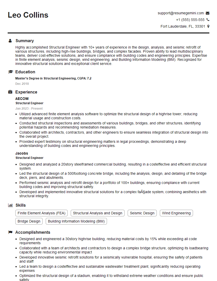
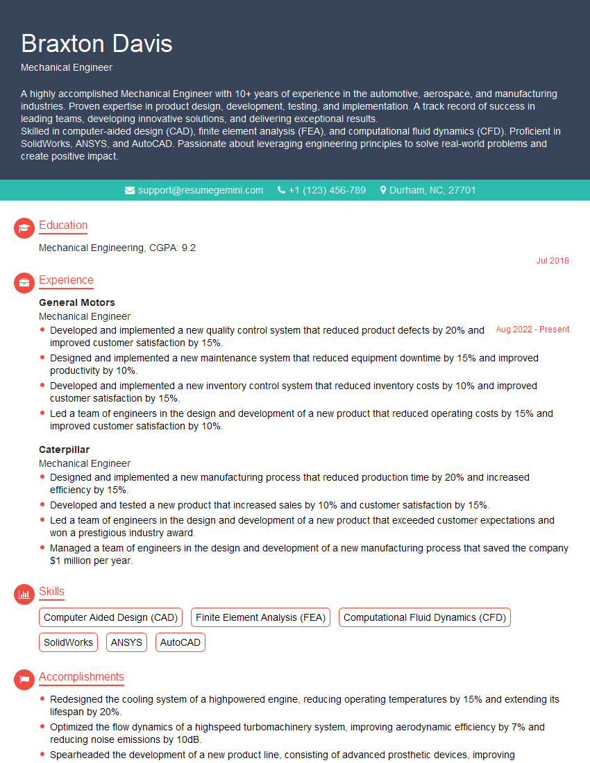
Mastering the principles of beam flange design and analysis is crucial for career advancement in structural engineering and related fields. A strong understanding of these concepts demonstrates a valuable skill set highly sought after by employers. To maximize your job prospects, create an ATS-friendly resume that effectively highlights your skills and experience. We recommend using ResumeGemini, a trusted resource, to build a professional and impactful resume. Examples of resumes tailored to the Beam Flanges field are available to help guide you through the process. Take the next step towards your dream career!
Explore more articles
Users Rating of Our Blogs
Share Your Experience
We value your feedback! Please rate our content and share your thoughts (optional).
What Readers Say About Our Blog
Interesting Article, I liked the depth of knowledge you’ve shared.
Helpful, thanks for sharing.
Hi, I represent a social media marketing agency and liked your blog
Hi, I represent an SEO company that specialises in getting you AI citations and higher rankings on Google. I’d like to offer you a 100% free SEO audit for your website. Would you be interested?
