Feeling uncertain about what to expect in your upcoming interview? We’ve got you covered! This blog highlights the most important Electrical Wiring and Repair interview questions and provides actionable advice to help you stand out as the ideal candidate. Let’s pave the way for your success.
Questions Asked in Electrical Wiring and Repair Interview
Q 1. Explain the National Electrical Code (NEC) and its importance.
The National Electrical Code (NEC) is a nationally recognized standard for safe electrical wiring and installation practices in the United States. Think of it as the rulebook for electricians. It’s crucial for ensuring safety, preventing electrical fires, and protecting both people and property. The NEC is regularly updated to reflect advancements in technology and safety standards. Ignoring the NEC can lead to serious consequences, including electrical shocks, fires, and even death. It dictates everything from wire sizing and circuit breaker selection to grounding requirements and installation methods. Compliance with the NEC is often mandated by local building codes and is essential for obtaining permits and insurance coverage for electrical work.
Q 2. Describe the different types of wiring used in residential construction.
Residential construction utilizes several wiring types, each suited to different needs. Common types include:
- Copper Romex (NM-B): This is the most common type, non-metallic sheathed cable, featuring two or more insulated conductors encased in a flexible plastic jacket. It’s readily available and easy to install, making it ideal for most residential wiring.
- Aluminum Romex (NM-AL): While less common now due to potential connection issues, aluminum wiring is sometimes found in older homes. It requires specialized connectors and techniques to prevent overheating and loose connections.
- BX (Flexible Metal Conduit): This type uses insulated conductors inside a flexible metal sheath, offering superior protection against physical damage. It’s often used in areas where the wiring might be subject to more wear and tear.
- MC Cable (Metal-Clad Cable): Similar to BX, but featuring a harder, more rigid outer sheath. It provides even better protection than BX.
- Conduit Wiring (Rigid or EMT): This involves running individual insulated wires within metal pipes. It’s highly durable and offers superior protection from damage but is more time-consuming to install.
Choosing the right wiring type depends on factors like the building’s age, intended use of the circuits, and local building codes. An improper choice can lead to hazards and increase the risk of electrical failure.
Q 3. How do you troubleshoot a faulty circuit breaker?
Troubleshooting a faulty circuit breaker involves a methodical approach. First, turn off the main breaker to ensure your safety. Then, visually inspect the breaker itself for any signs of damage, such as scorch marks or a tripped handle. If the breaker is tripped (the handle is in the ‘off’ position), carefully switch it back to the ‘on’ position. If it immediately trips again, there’s likely a short circuit or an overload on that circuit.
To find the cause:
- Check connected appliances and lights: Unplug or switch off everything on that circuit. If the breaker holds after that, you may have overloaded the circuit. Gradually plug back in items one at a time to isolate the culprit.
- Look for loose wires or damaged insulation: Inspect all connections in junction boxes and outlets served by the circuit breaker. Look for anything that appears loose, damaged, or worn.
- Check for grounded appliances: Ensure that no appliances are causing a ground fault (short to ground).
- If the problem persists, call a qualified electrician: Attempting more advanced troubleshooting without the proper skills and tools can be dangerous.
Remember: Electrical troubleshooting requires caution and respect for the potential dangers of working with electricity. Always prioritize safety first!
Q 4. What are the safety precautions when working with high voltage electricity?
Working with high-voltage electricity demands extreme caution. Never attempt high-voltage work without proper training and safety equipment. Here are some vital precautions:
- Lockout/Tagout Procedures: Always de-energize the circuit completely before working on it and use lockout/tagout procedures to prevent accidental re-energization. This is paramount to prevent electrical shock.
- Personal Protective Equipment (PPE): Wear appropriate PPE, including insulated gloves, safety glasses, and arc flash clothing, which is designed to protect against electrical burns. Never underestimate the importance of protective gear.
- Use Insulated Tools: Use only insulated tools that are rated for the voltage level you’re working with. Damaged or improperly insulated tools can become lethal.
- Proper Grounding: Ensure proper grounding to prevent stray voltage and reduce the risk of shock. Grounding is essential for safety.
- Awareness of Surroundings: Be mindful of your surroundings and ensure there are no potential hazards that could compromise your safety.
- Work with a Partner: Whenever possible, work with a partner to have someone available for assistance in case of an emergency.
High voltage poses a severe threat. Always err on the side of extreme caution.
Q 5. Explain the difference between AC and DC electricity.
AC (Alternating Current) and DC (Direct Current) are the two fundamental types of electricity. The key difference lies in the direction of electron flow.
- DC: Electrons flow in one constant direction. Think of a battery; it provides a steady flow of electrons from the positive to the negative terminal. DC is often used in electronic devices and battery-powered equipment.
- AC: Electrons flow back and forth, changing direction periodically. This is the type of electricity that comes from power plants and is commonly used in homes and businesses. The alternating nature of AC allows for efficient long-distance transmission with transformers.
Imagine a river: DC is like a river flowing steadily in one direction, while AC is like a tidal pool where the water flows back and forth with the tides. Both are forms of electrical energy, but their characteristics make them suitable for different applications.
Q 6. How do you test for continuity in a circuit?
Testing for continuity verifies if there’s an uninterrupted path for electricity to flow through a circuit. A multimeter is the essential tool. Set the multimeter to the continuity test setting (usually indicated by a diode symbol or ‘continuity’). Then, touch the multimeter’s leads to the two points you want to test. A continuous tone or reading indicates a complete circuit, meaning the electricity can flow unimpeded. No tone or a very high resistance reading indicates a break or open circuit. For example, you can use this to check the integrity of a wire or to confirm a connection between components. Before testing, always turn off power to the circuit being tested – safety first!
Example: Testing continuity of a wire. Touch one multimeter lead to one end of the wire and the other lead to the other end. A beep confirms a good connection.
Q 7. What are the different types of grounding methods?
Grounding is crucial for safety, providing a low-resistance path for fault currents to flow to the earth, preventing electrical shocks and fires. Several grounding methods exist:
- Grounding Rods: Driven into the earth, these provide a direct connection to the ground. Typically used for grounding systems in buildings and outdoor electrical equipment.
- Grounding Wires: These conductors connect electrical systems to a ground point, either a grounding rod or a metal water pipe. Grounding wires provide the path for fault currents to flow.
- Water Pipe Grounding (Less Common Now): Older buildings may utilize metallic water pipes as a ground path. However, due to the prevalence of plastic pipes, this method is less reliable and less frequently used now.
- Grounding Plates: Large metal plates buried in the earth, offering a significant surface area for grounding. Often used where soil conditions don’t facilitate effective rod grounding.
The specific grounding method used depends on the electrical system’s size, location, and local codes. Adequate grounding is non-negotiable for a safe electrical system.
Q 8. Describe your experience with conduit bending and installation.
Conduit bending and installation are fundamental skills in electrical work, ensuring safe and organized wiring. It involves shaping metal conduits – protective tubes for electrical wires – to navigate obstacles and create neat installations. My experience spans various conduit types, including EMT (electrical metallic tubing), rigid conduit, and flexible metal conduit. I’m proficient in using various bending tools like a hickey, bender, and hand-held bender, ensuring accurate bends to the specified radius. For example, I recently worked on a project where we had to snake conduit through a complex ceiling structure. Precise bending was crucial to avoid kinks that could damage wires. The process involves calculating the bend, marking the conduit, securely setting it in the bender, and applying consistent pressure until the desired angle is achieved. After bending, the conduit is installed, secured with appropriate clamps and straps, adhering to all local electrical codes.
I also have experience with installing various conduit fittings, including couplings, connectors, and boxes, ensuring a watertight and mechanically sound system. Proper installation is critical to prevent damage to the wiring and ensure worker and public safety.
Q 9. How do you identify and resolve common electrical panel problems?
Troubleshooting electrical panel problems requires a systematic approach, starting with visual inspection for any obvious issues like loose wires, tripped breakers, or signs of overheating (burnt wires, discoloration, unusual smells). I always begin by de-energizing the panel before any inspection or repair to ensure safety. Common problems include tripped breakers, which are usually easy to reset. However, a breaker that constantly trips indicates a potential short circuit or overload, requiring further investigation. Loose connections can cause arcing, a significant fire hazard. I check all connections meticulously, tightening them using appropriate tools. A faulty breaker itself might need replacement. I also check for any signs of water damage, which can cause shorts and electrocution risks. If there are any signs of extensive damage or if I encounter issues beyond my expertise, I always consult a senior electrician or call for professional help.
For instance, I once encountered a panel where repeated tripping of a specific breaker pointed to a faulty appliance. By meticulously tracing the circuit, I isolated the faulty device and advised the homeowner on its replacement, preventing further hazards.
Q 10. Explain the process of installing a new electrical outlet.
Installing a new electrical outlet involves several steps, all performed with the power switched off and verified as off. First, you locate the appropriate circuit in the electrical panel, ensuring the circuit is rated to handle the new outlet’s load. Next, you run the wiring from the panel to the desired location, following building codes and using appropriate conduit or cable routing. If extending an existing circuit, you’ll use wire nuts to securely connect the new wiring to the existing circuit. At the outlet location, you mount an electrical box, securing it to the wall structure according to the box’s instructions. Then, you carefully feed the wires through the knockout holes in the box. The outlet is then installed, with the ground wire connected to the ground terminal, the neutral wire connected to the neutral terminal (usually silver), and the hot wire connected to the hot terminal (usually brass). Finally, the outlet is secured in the box with screws, and the faceplate is installed. Always double-check all connections for tightness and accuracy before switching the power back on. A final test using a non-contact voltage tester confirms the correct operation.
Q 11. How do you diagnose and repair a short circuit?
Diagnosing a short circuit involves systematic investigation, always starting with safety precautions – de-energizing the circuit. A short circuit occurs when a live wire makes unintended contact with a neutral wire or ground, resulting in a surge of current. I typically use a multimeter to check continuity and voltage to isolate the problem area. Sometimes, a visual inspection can reveal damaged insulation, exposed wires, or loose connections. If a circuit breaker is frequently tripping, this is a strong indicator of a short. Using a circuit tracer, I can track the problematic wire run. Once the faulty section is identified, the repair involves fixing the damaged insulation, repairing or replacing the faulty wiring, and ensuring all connections are secure and properly insulated. After repairs, a thorough test with the multimeter is critical before re-energizing the circuit.
For example, I once traced a short circuit in an older home to a damaged wire hidden within the wall cavity. This required careful removal of sections of drywall to access and repair the damaged wiring, showcasing the importance of thorough investigation.
Q 12. What are the various types of electrical motors and their applications?
Electrical motors are widely used across various industries. They convert electrical energy into mechanical energy. There are several types, each with specific applications:
- DC Motors: Direct current motors are relatively simple and can provide precise speed control. They’re commonly found in smaller applications like fans, toys, and some power tools.
- AC Motors: Alternating current motors are more robust and are widely used in industrial settings. Sub-types include:
- Induction Motors: These are the most common type, known for their simplicity and reliability. They are used in many appliances (refrigerators, washing machines), industrial machinery, and pumps.
- Synchronous Motors: These motors run at a constant speed, synchronized with the power supply frequency. They’re used in applications requiring precise speed control, such as clocks and timing devices.
- Stepper Motors: Stepper motors allow precise rotational control in discrete steps, making them ideal for robotics and precision machinery.
- Servo Motors: These motors provide precise position control and are commonly used in robotics, industrial automation, and precision equipment.
The choice of motor depends heavily on the specific application requirements, considering factors such as power needs, speed control requirements, load characteristics, and operating environment.
Q 13. Describe your experience with electrical blueprints and schematics.
My experience with electrical blueprints and schematics is extensive. I can confidently read and interpret complex diagrams, understanding the layout of circuits, panel configurations, and wiring routes. These documents are essential for planning, installing, and troubleshooting electrical systems. I understand various symbols and notations used in electrical drawings, including those for components, wiring types, and circuit protection devices. I often use these blueprints and schematics to identify potential problems during inspections, plan new installations, and diagnose existing issues. For example, when working on a commercial renovation project, I used the electrical schematics to understand the existing wiring configuration before making any modifications, ensuring the project complied with all safety regulations and local codes.
Q 14. How do you ensure electrical safety in the workplace?
Electrical safety in the workplace is paramount. My approach is multifaceted, starting with adherence to all relevant safety regulations and codes. This includes using appropriate personal protective equipment (PPE) like insulated gloves, safety glasses, and non-contact voltage testers before working on any electrical equipment. I always ensure that the power is de-energized and locked out/tagged out before performing any work on energized circuits. Proper grounding and bonding are essential to mitigate electrical hazards. I meticulously inspect wiring and equipment for signs of damage, ensuring that all connections are secure and properly insulated. Regular safety meetings and training sessions are important for maintaining awareness among the team. Proper tools and equipment maintenance are crucial to prevent accidents. In addition, I promote a culture of safety by encouraging colleagues to report any potential hazards immediately and never hesitate to ask questions or seek clarification when needed.
Safety is not merely a checklist but a continuous mindset. A vigilant attitude ensures that everyone goes home safe at the end of the day.
Q 15. Explain the difference between series and parallel circuits.
The key difference between series and parallel circuits lies in how the components are connected and how the current flows. In a series circuit, components are connected end-to-end, forming a single path for current. Imagine it like a single lane road – all traffic (current) must travel through the same path. If one component fails, the entire circuit breaks.
A parallel circuit, on the other hand, has multiple paths for current to flow. Think of it as a multi-lane highway. If one lane (component) is blocked, the traffic (current) can still flow through other lanes. Components in parallel maintain their individual voltage, while the current splits among the branches.
- Series Circuit: Total resistance is the sum of individual resistances (Rtotal = R1 + R2 + R3…). The current is the same through all components. The voltage is divided across the components.
- Parallel Circuit: The reciprocal of the total resistance is the sum of the reciprocals of individual resistances (1/Rtotal = 1/R1 + 1/R2 + 1/R3…). The voltage is the same across all components. The current is divided among the components.
For example, Christmas tree lights are often wired in series – one bulb burns out, and the whole string goes dark. Household circuits, however, are wired in parallel, so a malfunctioning appliance doesn’t affect the others.
Career Expert Tips:
- Ace those interviews! Prepare effectively by reviewing the Top 50 Most Common Interview Questions on ResumeGemini.
- Navigate your job search with confidence! Explore a wide range of Career Tips on ResumeGemini. Learn about common challenges and recommendations to overcome them.
- Craft the perfect resume! Master the Art of Resume Writing with ResumeGemini’s guide. Showcase your unique qualifications and achievements effectively.
- Don’t miss out on holiday savings! Build your dream resume with ResumeGemini’s ATS optimized templates.
Q 16. How do you calculate voltage, current, and resistance using Ohm’s Law?
Ohm’s Law is a fundamental principle in electrical engineering, describing the relationship between voltage (V), current (I), and resistance (R). The formula is: V = I * R
This means voltage is directly proportional to current and resistance. We can rearrange this formula to solve for any of the three variables:
- To find Voltage (V): Multiply the current (I) by the resistance (R).
V = I * R - To find Current (I): Divide the voltage (V) by the resistance (R).
I = V / R - To find Resistance (R): Divide the voltage (V) by the current (I).
R = V / I
Example: A light bulb has a resistance of 10 ohms (Ω) and a current of 2 amps (A) flowing through it. To find the voltage across the bulb, we use the formula: V = I * R = 2A * 10Ω = 20V. The voltage across the bulb is 20 volts.
Q 17. What are the common causes of electrical fires and how to prevent them?
Electrical fires are a serious hazard, often stemming from a combination of factors. Some common causes include:
- Overloaded circuits: Plugging too many appliances into one outlet or circuit can cause overheating and potentially start a fire. This is why we use circuit breakers – they trip when the current exceeds a safe level.
- Faulty wiring: Damaged or improperly installed wiring can create sparks and generate enough heat to ignite nearby materials. This often results from old, deteriorated wiring or poor workmanship during installation.
- Short circuits: A short circuit occurs when a live wire makes direct contact with a neutral or ground wire, resulting in a sudden surge of current and significant heat generation. This can be caused by damaged insulation or accidental contact.
- Appliance malfunctions: Defective appliances can overheat and cause fires. Always check for frayed cords and damaged parts, and have appliances regularly inspected.
Prevention strategies are crucial and include:
- Regular electrical inspections: Have a qualified electrician inspect your wiring periodically to identify potential hazards before they become problems.
- Proper use of extension cords: Avoid overloading extension cords and use appropriate gauge cords for the load. Never run extension cords under rugs or carpets.
- GFCI outlets: Ground Fault Circuit Interrupters (GFCIs) are essential in bathrooms, kitchens, and outdoor locations, immediately cutting power in case of a ground fault and preventing shocks and fires.
- Avoid overloading circuits: Use surge protectors and power strips appropriately. Be mindful of the total amperage draw from each circuit.
By addressing these causes and implementing preventative measures, you significantly reduce the risk of electrical fires.
Q 18. Describe your experience working with different types of electrical tools.
Throughout my career, I’ve extensively used various electrical tools, from basic hand tools to sophisticated testing equipment. My experience encompasses:
- Hand Tools: Screwdrivers (Phillips and flathead), wire strippers, pliers (lineman’s, needle-nose), crimpers, voltage testers, and fish tape are essential for everyday tasks like installing outlets, repairing wiring, and troubleshooting circuits.
- Power Tools: I’m proficient with drills (both corded and cordless), reciprocating saws, and hole saws for installing conduit and junction boxes. Safety is paramount when using power tools; I always wear appropriate safety gear including eye protection and gloves.
- Testing Equipment: I routinely use multimeters (both analog and digital) to measure voltage, current, and resistance. Clamp meters are invaluable for measuring current without disconnecting wires. I also have experience with insulation resistance testers (meggers) to assess the integrity of wiring insulation and ground fault circuit interrupters (GFCIs) testers.
My experience includes using these tools in various settings: residential, commercial, and industrial. I understand the importance of selecting the right tool for the job and following all safety protocols to minimize risks. A recent project involved tracing a faulty wire in a complex commercial setting; using a combination of a tone generator and a signal tracer allowed me to quickly locate and repair the problem, preventing further disruptions.
Q 19. How do you test for ground faults?
Testing for ground faults is critical for ensuring safety and preventing electrical shocks. Ground faults occur when current leaks from a live wire to ground, often due to damaged insulation or a faulty appliance. The most common method uses a Ground Fault Circuit Interrupter (GFCI), a safety device that detects imbalances in current flow between the hot and neutral wires. If an imbalance exceeding a specified threshold is detected (typically 5 mA), the GFCI instantly cuts off the power, preventing shocks or fires.
Testing a GFCI: GFCIs have a built-in test button. Pressing this button should trip the GFCI, and restoring power should verify its correct operation. It is crucial to regularly test GFCIs in high-risk areas such as bathrooms, kitchens, and outdoor outlets.
Beyond GFCIs, a multimeter can be used to detect ground faults by checking for the presence of voltage on the ground wire. A reading on a ground wire indicates a potential ground fault that requires immediate attention and repair. Remember always to de-energize the circuit before performing any tests.
In more complex scenarios, specialized testing equipment, such as a ground fault loop impedance tester, might be needed to assess the integrity of the entire grounding system. These sophisticated tools are crucial in industrial environments and for determining compliance with electrical codes.
Q 20. What are the different types of transformers and their functions?
Transformers are essential components in electrical systems, primarily used to change the voltage of an alternating current (AC) supply. They operate on the principle of electromagnetic induction. Different types of transformers exist, each serving a specific purpose:
- Step-up Transformers: These increase the voltage. They have more turns in the secondary winding than in the primary winding. A common application is in power transmission, where high voltage reduces power loss over long distances.
- Step-down Transformers: These decrease the voltage. They have fewer turns in the secondary winding than in the primary winding. These are commonly used in household appliances and electronics to step down the high voltage from the power grid to safer levels (e.g., 120V or 240V to lower voltages).
- Isolation Transformers: These provide electrical isolation between the primary and secondary windings, preventing the flow of ground currents. They’re crucial in sensitive equipment to prevent ground loops and maintain safety.
- Autotransformers: These have a single winding shared by both the primary and secondary circuits. They are less expensive than other transformers but do not provide electrical isolation.
- Instrument Transformers: These are specialized transformers used for metering and protection purposes. Current transformers (CTs) measure current, while potential transformers (PTs) measure voltage.
The choice of transformer type depends on the specific application and the required voltage transformation and isolation characteristics.
Q 21. Explain your experience with electrical load calculations.
Accurate electrical load calculations are crucial for designing safe and efficient electrical systems. It involves determining the total power consumption of all devices and appliances within a circuit or building. My experience includes using various methods for load calculations, depending on the complexity of the system.
For simple circuits, calculating the load involves summing up the individual power ratings (wattage) of all the connected devices. For instance, summing the wattage of lights, outlets, and appliances on a given circuit is a straightforward approach. However, it’s important to consider factors like the power factor (for AC loads) and the demand factor, which accounts for the fact that not all loads are simultaneously active.
In more complex scenarios, such as commercial buildings, I use specialized software and detailed load schedules to perform a more comprehensive analysis. These programs consider factors like peak demand, diversity, and future expansion needs. I also need to take into account the type of electrical system (e.g., single-phase, three-phase), the voltage levels, and the required safety factors to ensure that the wiring and circuit breakers have sufficient capacity.
A recent project involved calculating the load for a large commercial kitchen. By using a dedicated electrical load calculation software and consulting with the kitchen designers, I was able to accurately determine the required power capacity, size the appropriate transformers, and design a robust and safe electrical system that met all applicable codes.
Q 22. Describe your experience with different types of switches and their applications.
My experience encompasses a wide range of switches, from simple single-pole switches to complex multi-way and smart switches. A single-pole switch, the most common type, controls a light from one location. Think of the basic light switch in your home. A double-pole switch controls two separate circuits from a single location, often used for larger appliances or to switch both sides of a 240V circuit. Three-way switches allow control of a light from two different locations – very handy on staircases. Four-way switches are added to extend this control to three or more locations. Smart switches, integrated with home automation systems, offer features like remote control, scheduling, and energy monitoring. In industrial settings, I’ve worked with heavy-duty switches rated for higher currents and voltages, as well as switches designed for specific applications like motor control or emergency stops. The selection of the appropriate switch always depends on the load, voltage, and safety requirements of the circuit.
- Single-Pole: Basic on/off control from one location.
- Double-Pole: Controls two circuits from one location.
- Three-Way: On/off control from two locations.
- Four-Way: Extends three-way control to additional locations.
- Smart Switches: Offer remote control and automation features.
Q 23. How do you troubleshoot a faulty lighting fixture?
Troubleshooting a faulty lighting fixture involves a systematic approach. First, I’d ensure the power is OFF at the breaker. Then, I visually inspect the fixture for loose wires, damaged components (like the socket or switch), and any obvious physical damage. Next, I’d check the voltage at the fixture using a non-contact voltage tester and a multimeter to confirm power is reaching the fixture. If power is present, I’d carefully examine the connections at the fixture, looking for loose or corroded wires. If the problem persists, I’d test the fixture itself by replacing the bulb (a simple fix that’s often overlooked) and examining the socket for defects. If the issue remains, I’d check the switch to rule out a faulty switch before examining the circuit wiring further back towards the breaker. Proper documentation and safety procedures are critical throughout the process.
For example, I once worked on a fixture where the light wouldn’t turn on. After visually inspecting the fixture and confirming power at the breaker, I discovered a loose wire connection at the fixture itself. Tightening it immediately resolved the issue. It’s important to always remember that safety comes first, and working with live wires is extremely dangerous.
Q 24. What are the different types of circuit protection devices?
Circuit protection devices prevent damage to electrical equipment and prevent fires by interrupting the flow of current when an overload or short circuit occurs. The most common types are:
- Circuit Breakers: These are reusable devices that automatically trip when a fault is detected, cutting off power to the circuit. They can be thermal or magnetic, or a combination of both, to respond to different types of faults. Thermal breakers react to heat caused by excessive current, while magnetic breakers react to high current flow.
- Fuses: These are one-time use devices containing a wire that melts and breaks the circuit when excessive current flows. They are simpler than circuit breakers but need replacing after they trip.
- Ground Fault Circuit Interrupters (GFCIs): These are designed to detect small imbalances in current flow, protecting against electrical shocks. They’re commonly used in areas with high moisture, such as bathrooms and kitchens.
- Arc Fault Circuit Interrupters (AFCIs): These are designed to detect and interrupt arcing faults, which can cause fires. Often found in bedrooms and hallways.
The choice of device depends on the specific application and safety requirements. Industrial settings often utilize more specialized protective devices such as motor protection relays or surge suppressors to handle larger loads and protect sensitive equipment.
Q 25. Explain your experience with troubleshooting and repairing industrial control systems.
My experience with industrial control systems includes troubleshooting Programmable Logic Controllers (PLCs), Human-Machine Interfaces (HMIs), and various motor control systems. Troubleshooting often involves using diagnostic tools to identify the source of the problem. This could involve checking sensor inputs, examining PLC program logic, and verifying output signals to actuators. I’ve utilized logic analyzers, oscilloscopes, and multimeter to diagnose problems with both hardware and software. For example, I once diagnosed a production line stoppage by isolating a faulty sensor input causing the PLC to shut down the entire line. Replacing the faulty sensor quickly restored operations. Experience with ladder logic and other programming languages is critical for debugging and modifying PLC programs. Safety is paramount in industrial settings, and I follow strict lockout/tagout procedures to avoid electrical hazards.
Q 26. Describe your experience with preventative maintenance of electrical systems.
Preventative maintenance is crucial for ensuring the safety and reliability of electrical systems. My approach involves regular inspections, testing, and cleaning to identify potential problems before they cause failures. This includes visually inspecting wiring and connections for damage or corrosion, testing insulation resistance, and verifying the proper operation of circuit breakers and other safety devices. Thermal imaging can help detect overheating components before they fail. Regular cleaning of electrical enclosures removes dust and debris which can lead to overheating and fires. I also create and maintain detailed documentation of maintenance activities for efficient tracking and planning of future maintenance tasks. Following manufacturers’ recommendations and developing a customized schedule tailored to the specific system is key to a successful preventative maintenance program.
For example, a regular inspection might uncover loose connections on a motor controller, preventing a potential arc flash and system failure. The key is early detection of potential problems.
Q 27. How do you handle emergency situations involving electrical hazards?
Handling emergency situations involving electrical hazards requires immediate action and a focus on safety. The first step is always to isolate the power source by switching off the relevant circuit breaker or disconnecting the power supply if possible. If someone is in contact with live wires, I would NOT approach them directly. Instead, I’d immediately call emergency services and use non-conductive materials to try to separate the person from the electrical source while ensuring my own safety. Once the power is off, I would assess the situation and determine the extent of the damage and injuries. Safety training is critical in handling these situations, emphasizing the proper use of Personal Protective Equipment (PPE) such as insulated gloves and tools. Thorough documentation of the incident is also essential for future investigations and preventing similar occurrences.
Remember, safety is always paramount. Never attempt to handle a live electrical hazard without proper training and safety precautions.
Key Topics to Learn for Electrical Wiring and Repair Interview
- Electrical Codes and Regulations: Understanding and applying relevant national and local electrical codes (e.g., NEC) is crucial for safe and compliant work. This includes understanding grounding, bonding, and circuit protection.
- Wiring Methods and Techniques: Mastering various wiring methods (e.g., Romex, conduit, surface mount) and techniques, including wire stripping, splicing, and termination, is essential for practical application. Consider different wire types and their applications.
- Troubleshooting and Diagnostics: Develop strong troubleshooting skills to identify and resolve electrical faults using multimeters, voltage testers, and other diagnostic tools. Practice analyzing symptoms and identifying potential causes.
- Blueprint Reading and Schematic Interpretation: Ability to interpret electrical blueprints, schematics, and diagrams is vital for understanding and executing wiring installations and repairs. Practice reading and interpreting various types of electrical drawings.
- Electrical Safety Procedures: Prioritizing safety is paramount. Demonstrate a thorough understanding of lockout/tagout procedures, personal protective equipment (PPE), and safe work practices. This includes understanding arc flash hazards and mitigation.
- Motor Controls and Circuits: Understanding the principles of motor operation, control circuits (starters, relays, timers), and troubleshooting motor-related issues is important for many applications.
- Residential and Commercial Wiring Systems: Familiarize yourself with the differences in wiring practices and requirements for residential versus commercial settings.
- Common Electrical Components and Their Function: Develop a strong understanding of various electrical components such as circuit breakers, fuses, switches, receptacles, and their functionalities.
Next Steps
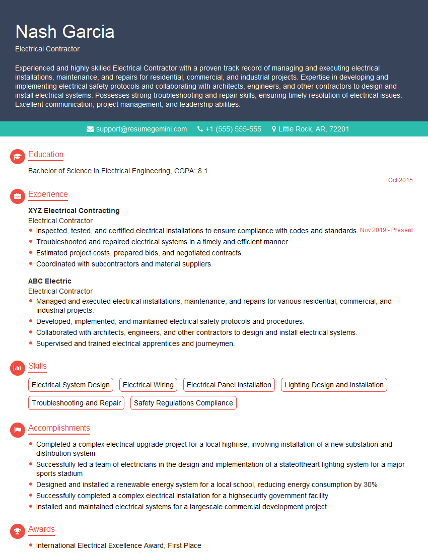
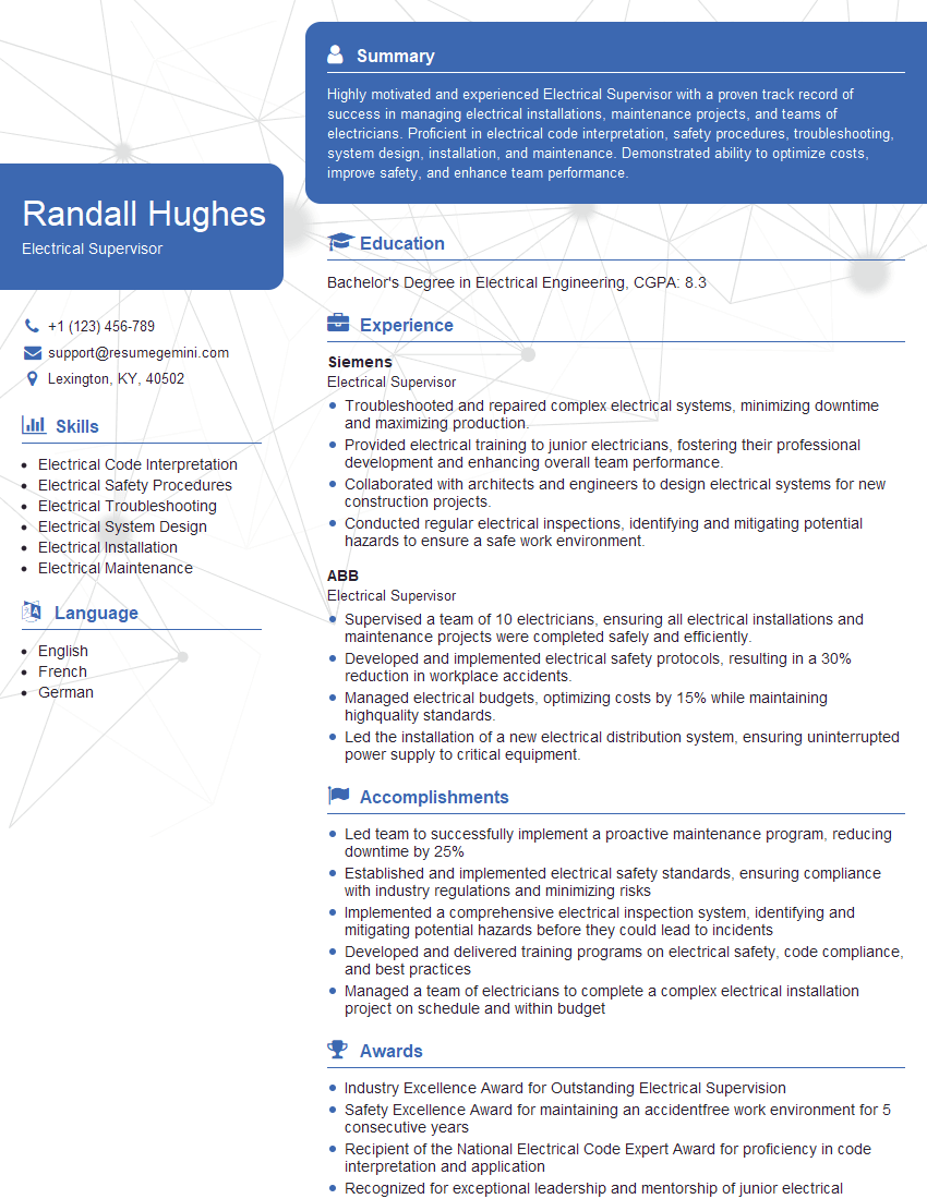
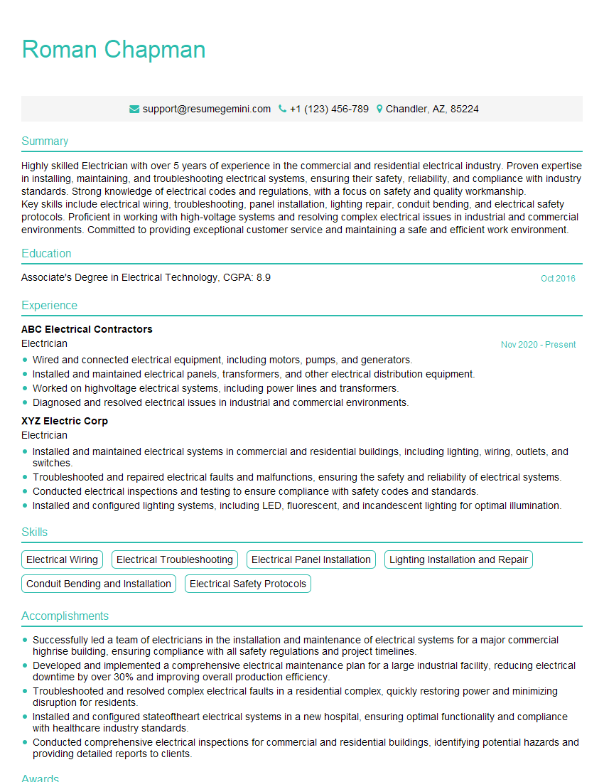
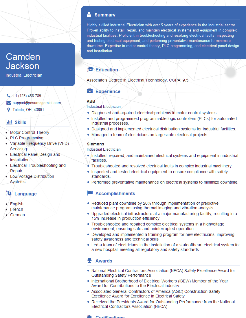
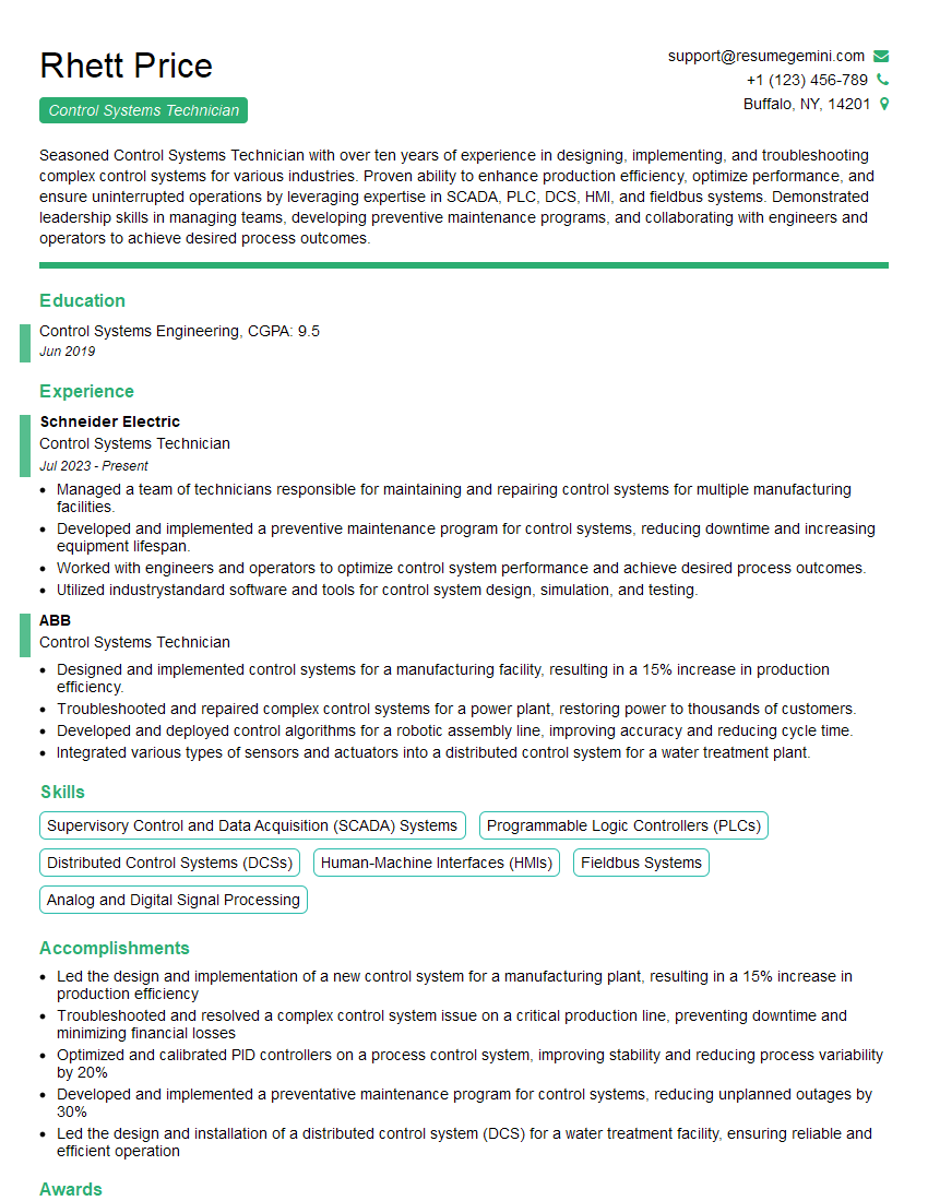
Mastering Electrical Wiring and Repair opens doors to a rewarding and stable career with excellent growth potential. Your expertise will be in high demand across various industries. To maximize your job prospects, creating a strong, ATS-friendly resume is essential. ResumeGemini is a trusted resource that can help you build a professional resume that showcases your skills and experience effectively. They provide examples of resumes tailored specifically to the Electrical Wiring and Repair field, ensuring your application stands out. Invest time in crafting a compelling resume to significantly improve your chances of landing your dream job.
Explore more articles
Users Rating of Our Blogs
Share Your Experience
We value your feedback! Please rate our content and share your thoughts (optional).
What Readers Say About Our Blog
Live Rent Free!
https://bit.ly/LiveRentFREE
Interesting Article, I liked the depth of knowledge you’ve shared.
Helpful, thanks for sharing.
Hi, I represent a social media marketing agency and liked your blog
Hi, I represent an SEO company that specialises in getting you AI citations and higher rankings on Google. I’d like to offer you a 100% free SEO audit for your website. Would you be interested?
