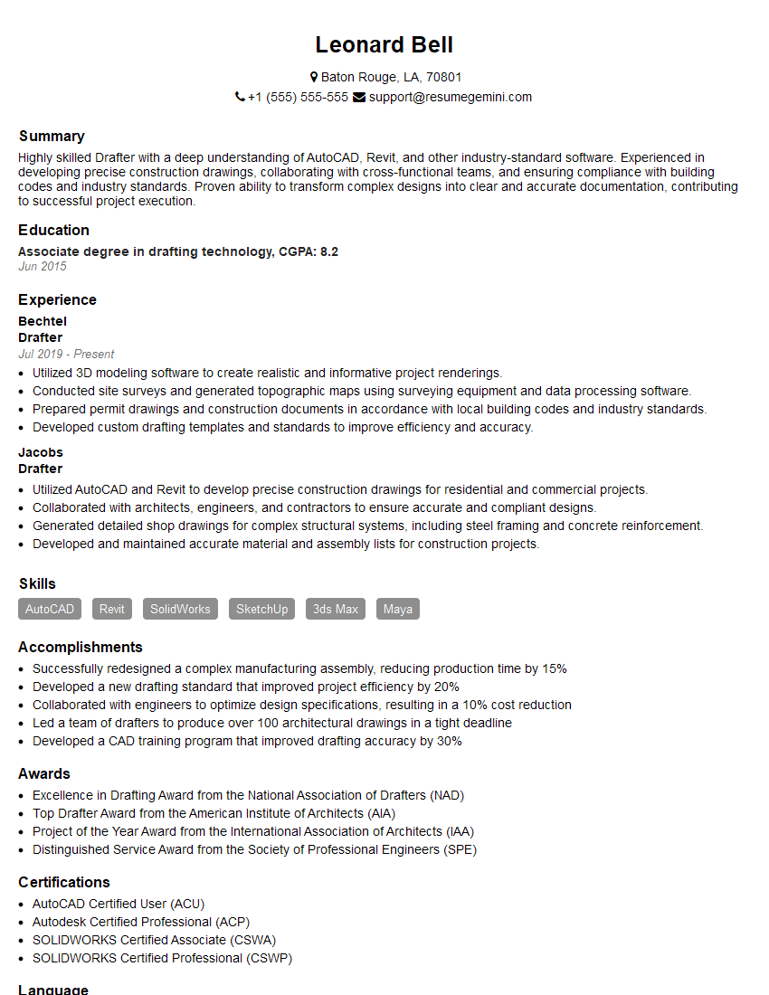
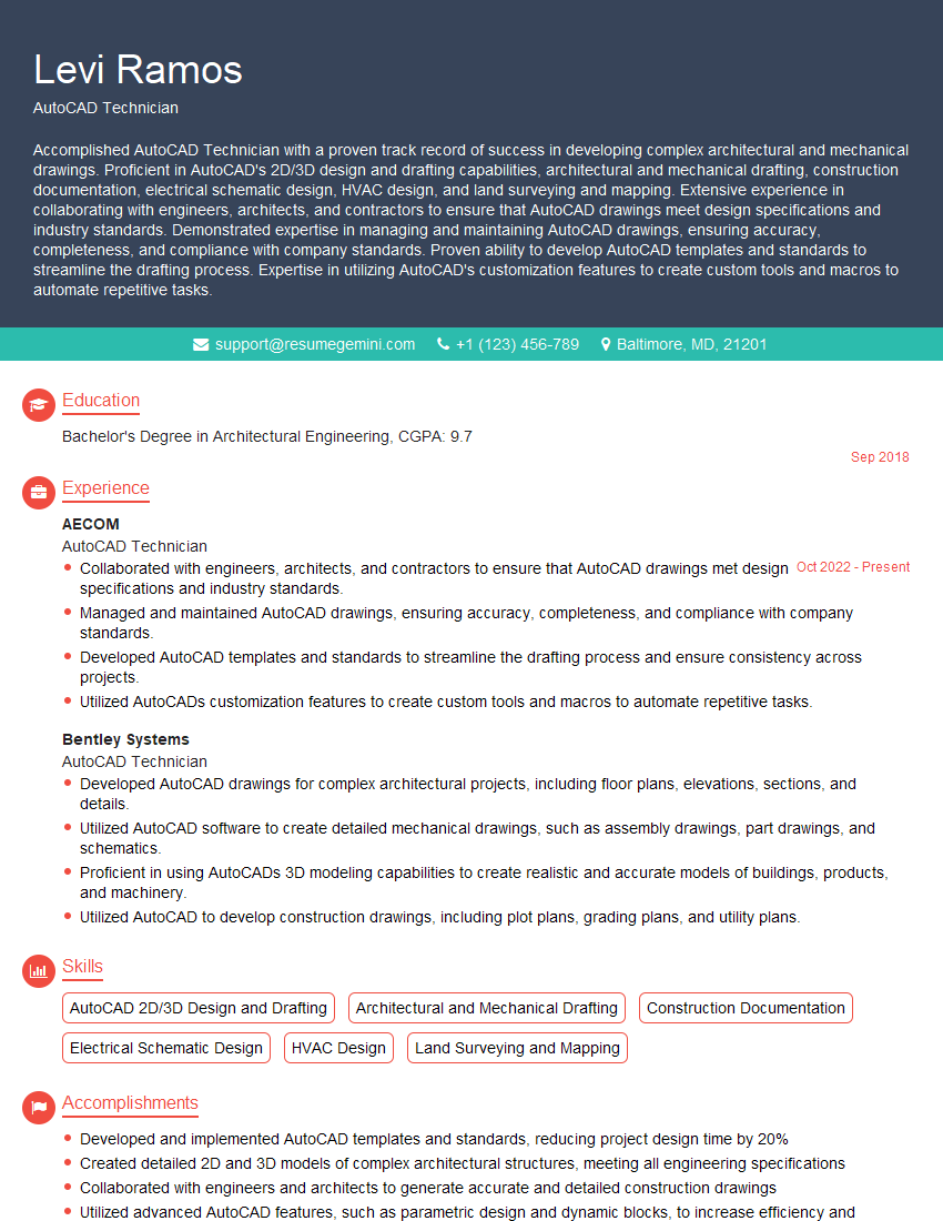
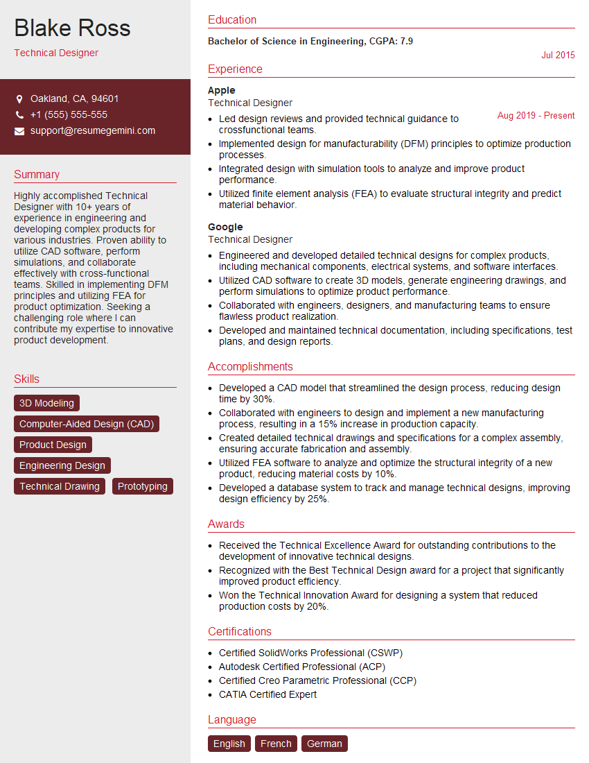
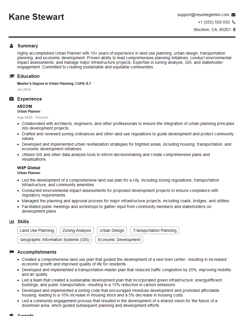
Are you ready to stand out in your next interview? Understanding and preparing for Strong understanding of architectural drawings interview questions is a game-changer. In this blog, we’ve compiled key questions and expert advice to help you showcase your skills with confidence and precision. Let’s get started on your journey to acing the interview.
Questions Asked in Strong understanding of architectural drawings Interview
Q 1. Explain the difference between floor plans, elevations, and sections.
Architectural drawings employ several key view types to convey design information comprehensively. Floor plans, elevations, and sections each serve a unique purpose, offering different perspectives of the building.
Floor Plans: These are horizontal ‘slices’ through a building, typically showing the arrangement of rooms, walls, doors, windows, and fixtures from a bird’s-eye view. Imagine looking down on a building after removing the roof – that’s essentially a floor plan. They are crucial for understanding spatial relationships and circulation.
Elevations: Elevations are vertical ‘slices’ of a building’s exterior walls. They provide a detailed view of the building’s facade, showcasing windows, doors, materials, and other exterior features from a specific direction. Think of them as photographs taken directly facing a wall. They are important for aesthetic considerations and detailing exterior finishes.
Sections: Sections are vertical ‘cuts’ through a building, revealing the interior structure and relationships between different levels. They show how the building is constructed, displaying the thickness of walls, locations of stairs, and the relative heights of different elements. Imagine slicing a cake – the resulting cut surface represents a section. They are indispensable for understanding the building’s three-dimensional organization and structural components.
For example, a floor plan might show the layout of a kitchen, an elevation will illustrate the design of the front of the house, and a section will show the placement of beams and joists within the ceiling.
Q 2. Describe your experience using various CAD software (e.g., AutoCAD, Revit).
My experience with CAD software spans over ten years, encompassing extensive use of AutoCAD and Revit. I’ve leveraged AutoCAD primarily for 2D drafting, creating detailed floor plans, elevations, sections, and construction documents. I’m proficient in utilizing layers, linetypes, text styles, and dimensioning to produce clean and accurate drawings.
Revit, on the other hand, has been instrumental in my work on more complex projects involving Building Information Modeling (BIM). I’m adept at creating 3D models, using Revit’s parametric capabilities to efficiently modify designs and generate various documentation sets, including schedules and quantities. I can easily coordinate various disciplines through linked models. For example, I’ve utilized Revit to create a full BIM model for a large multi-family residential project, allowing for seamless collaboration with structural, mechanical, electrical, and plumbing engineers.
Beyond these two, I have familiarity with other software including SketchUp for quick conceptual models and Adobe Illustrator for graphic design and presentation materials.
Q 3. How do you interpret scale in architectural drawings?
Scale in architectural drawings represents the ratio between the dimensions on the drawing and the actual dimensions of the building. It is typically expressed as a ratio, such as 1:100 or 1/4″ = 1′. This means that 1 unit on the drawing represents 100 units in reality, or 1/4 inch on the drawing equals 1 foot in the actual building.
Interpreting scale involves using a scale rule or measuring the drawing with a ruler and then applying the scale ratio to determine the true dimensions. For instance, if a wall measures 5 inches on a drawing with a scale of 1:50, the actual wall length is 5 inches * 50 = 250 inches, or 20 feet 10 inches.
Incorrect scale interpretation can lead to significant errors during construction, making it crucial to understand and apply the correct scale consistently throughout the project.
Q 4. What are typical drawing sheet sizes and their applications?
Standard drawing sheet sizes vary depending on the region and project requirements, but common sizes include ANSI (American National Standards Institute) and ISO (International Organization for Standardization) formats.
ANSI: Common sizes include A (8.5″ x 11″), B (11″ x 17″), C (17″ x 22″), D (22″ x 34″), and E (34″ x 44″). These are often used for smaller projects or individual drawings. Larger sheets (D and E sizes) are frequently used for complex floor plans or site plans.
ISO: The ISO A-series (A0, A1, A2, A3, A4) is widely adopted internationally. A0 is the largest and the rest are derived by halving the preceding size. This system provides a consistent and scalable approach. For example, A1 is often used for floor plans while A3 is suitable for details.
The choice of sheet size depends on the level of detail and the amount of information needed to be conveyed. Larger sheets are usually employed for complex plans requiring greater detail, while smaller sheets are sufficient for simpler drawings or details.
Q 5. Explain the significance of different line weights in architectural drawings.
Line weights in architectural drawings are crucial for conveying hierarchy and clarity. Different thicknesses represent various elements or information, making it easier to distinguish between objects and their significance. Thicker lines generally represent more important elements.
Thick Lines: Often used for exterior walls, primary structural elements, and major features. This emphasizes their importance within the drawing.
Medium Lines: Used for interior partitions, smaller structural members, and details that require prominence but less emphasis than primary elements.
Thin Lines: Typically used for dimensions, notes, section lines, and minor details. They help to avoid visual clutter without sacrificing essential information.
Consistent line weight usage is vital for creating clear and easily understandable drawings. Inconsistent line weights can lead to confusion and misinterpretations, potentially resulting in construction errors.
Q 6. How do you identify and interpret common architectural symbols?
Architectural drawings employ a standardized set of symbols to represent various elements efficiently. These symbols are usually depicted in legends or symbol keys within the drawings. Familiarity with these symbols is essential for accurate interpretation.
For instance, a filled black square might represent a door, while a dashed line could indicate a center line. A circle with a cross inside could represent a fixture, and different line patterns could denote different wall types (e.g., solid line for masonry walls, dashed line for curtain walls).
Proficiency in identifying and interpreting these symbols is crucial for understanding the relationships between different architectural elements and for accurately extracting information from the drawings. I have developed this skill through extensive experience in reviewing and creating architectural drawings, supplemented by referencing widely accepted standards and symbol guides.
Q 7. Describe your process for reviewing and checking architectural drawings for errors.
My process for reviewing architectural drawings involves a systematic approach to ensure accuracy and completeness. I typically follow these steps:
Initial Overview: I begin by reviewing the drawings at a high level, checking for overall consistency and completeness. I verify that all required sheets are present and that the project information is accurate.
Detailed Check: I then proceed to a detailed check, focusing on individual elements, dimensions, and annotations. I meticulously compare plans, sections, and elevations to identify discrepancies. This involves verifying dimensions, checking for clashes between different elements, and ensuring that the drawings conform to relevant building codes and regulations. Tools like coordination software can be helpful here.
Calculations and Verification: I perform calculations to confirm the accuracy of areas, volumes, and other critical parameters. For example, I will check if the total area of the floor plans matches the area calculations obtained from the architectural model.
Consistency Check: Ensuring consistency throughout the drawings is critical. I check for consistency of materials, finishes, and other attributes across different sheets. For instance, I would verify that the wall types and finishes are consistent across multiple floor plans.
Documentation of Errors: All identified errors and discrepancies are documented with clear explanations and suggestions for correction. This documentation is then shared with the design team for review and action.
This methodical approach minimizes the risk of errors during construction and ensures that the drawings accurately reflect the design intent. Regular checks and revisions are crucial for any architectural project to ensure it meets all requirements and standards.
Q 8. How familiar are you with building codes and regulations as they relate to drawings?
Building codes and regulations are paramount in architectural drawings. My familiarity extends to a deep understanding of codes like IBC (International Building Code), local ordinances, and accessibility standards (ADA). I ensure all drawings comply with these regulations. For instance, I meticulously check egress routes, fire-rated walls, and accessibility requirements, referencing the specific code sections throughout the design process. I don’t just passively adhere; I proactively incorporate code compliance into the design from the initial conceptual phase to avoid costly revisions later. This involves understanding the implications of different code interpretations and selecting the best design solutions within those constraints.
A practical example would be designing a stairway: I would ensure the riser and tread dimensions adhere to code-specified limits, allowing for safe and compliant access. This also includes detailing handrails, considering the width of the staircase based on occupancy loads, and designing landings to meet specific requirements. I regularly update my knowledge by staying current with code changes and attending relevant professional development courses.
Q 9. How do you handle revisions and updates to architectural drawings?
Revisions and updates are handled using a rigorous system that ensures accuracy and prevents errors. We use a version control system—typically integrated within our BIM software—to track changes. Each revision is clearly documented with a revision number, date, description of changes, and the initials of the responsible person. This creates a detailed audit trail, essential for tracking progress and resolving discrepancies.
When handling revisions, I focus on clearly marking changes on the drawings—using redlines, revision clouds, or other visual cues for clear identification. This is crucial for ensuring all stakeholders—contractors, engineers, and clients—understand the modifications. Furthermore, all impacted drawings are updated simultaneously to maintain consistency. This avoids confusion and ensures the entire set remains synchronized. Before releasing any revised drawing set, we conduct a thorough internal review to catch any oversights.
Q 10. What are your preferred methods for organizing and managing large sets of drawings?
For organizing and managing large sets of drawings, I utilize a combination of cloud-based storage solutions and a robust project management system. Cloud storage allows for easy access and collaboration, while the project management system provides a structured framework. I typically organize drawings using a hierarchical system based on discipline (Architectural, Structural, MEP), building number, floor, and sheet number.
For example, a typical naming convention might be Project Name_Discipline_Building_Floor_Sheet Number_Revision.pdf (e.g., Office Tower_Architectural_A_01_001_RevB.pdf). This ensures easy retrieval of specific documents, streamlining the process and minimizing searching time. This clear organization is crucial for efficient collaboration and avoids confusion, especially in complex projects. We also use metadata tagging to further categorize and quickly search for specific information within the drawings.
Q 11. Explain your experience with BIM (Building Information Modeling).
My experience with BIM (Building Information Modeling) is extensive. I’m proficient in various BIM software, including Revit and ArchiCAD. I leverage BIM for everything from initial design concepts to detailed construction documentation and even post-construction analysis. BIM’s ability to create a central, coordinated model is invaluable.
I’ve used BIM to manage complex projects, identifying clashes between different disciplines (MEP and structural) early on, which allows for timely resolution, minimizing costly rework during construction. For example, detecting a clash between a ductwork and a structural beam in the model allows us to adjust the design before construction starts, avoiding delays and cost overruns. Beyond clash detection, BIM helps in quantity take-offs, cost estimations, and creating simulations for various building performance aspects. It’s more than just 3D modeling; it’s a comprehensive management tool transforming the entire design and construction workflow.
Q 12. How do you use architectural drawings to coordinate with other disciplines (e.g., structural, MEP)?
Coordination with other disciplines is a crucial aspect of my workflow, and architectural drawings are the central communication tools. Using BIM software significantly simplifies this process. The coordinated model ensures that all disciplines work from a single source of truth, minimizing errors and conflicts. We regularly hold coordination meetings with structural, MEP, and other consultants to review the model and resolve any clashes or discrepancies.
Beyond the digital model, I create clear and concise drawings with precise dimensions and notations that highlight key coordination points. For example, I use section drawings to clearly show the relationship between architectural elements and structural systems or indicate the precise location of MEP penetrations. This collaborative approach guarantees that all aspects of the building are seamlessly integrated, leading to a smoother construction process and a higher-quality finished product. Clear communication is key, often including markups and annotations directly on the drawings to highlight specific issues or design considerations.
Q 13. How do you ensure drawings are clear, concise and meet industry standards?
Ensuring drawings are clear, concise, and meet industry standards is a top priority. I adhere to established drafting standards (like ANSI) and use consistent formatting throughout the entire drawing set. This ensures readability and reduces ambiguity.
My approach involves using clear and concise labeling, employing a consistent scale and line weight, and utilizing appropriate symbols and annotations. For instance, I use legends to explain symbols, and notes are precise and unambiguous, leaving no room for misinterpretation. Furthermore, I incorporate visual cues like callouts and cross-referencing to guide the viewer through the drawings. Regular quality checks are performed throughout the process, and peers review the drawings before finalization to ensure they meet the highest standards of clarity and accuracy.
Q 14. Describe your experience in creating detailed construction documents.
Creating detailed construction documents is a core part of my experience. This involves producing a complete set of drawings that clearly and accurately communicate all necessary information to the construction team. The level of detail is crucial for successful construction.
My process typically includes plans, sections, elevations, details, schedules, and specifications. I pay close attention to dimensions, materials, finishes, and construction techniques. For example, a detail drawing would clearly depict the construction method of a complex wall assembly, specifying the order of layers, materials, and fastening details. I’ve worked on projects ranging from small renovations to large-scale commercial buildings, always striving to provide a drawing set that minimizes ambiguity and leaves no room for errors during construction. This ensures the final product matches the design intent, saving time and costs during construction.
Q 15. How do you communicate effectively using architectural drawings with clients and contractors?
Communicating effectively with clients and contractors using architectural drawings requires a multi-faceted approach focusing on clarity, visual aids, and active listening. I start by understanding their level of architectural knowledge. For clients with limited experience, I use simple language, avoiding jargon, and rely heavily on visuals. I’ll walk them through key features using annotated drawings, highlighting crucial aspects like room sizes, material choices, and overall spatial flow. For contractors, detailed drawings are paramount. We’ll focus on construction details, specifications, and material callouts to ensure consistent understanding and error-free execution. Regular meetings, where we collaboratively review drawings and address concerns, are essential for seamless communication and project success.
For example, when presenting to a client, I might use a 3D model alongside a floor plan to show them how the spaces relate. With contractors, I’d emphasize sections and details to ensure the construction is accurate and meets the design intent. Active listening throughout the process is key, enabling me to address concerns and refine the drawings to align with everyone’s needs.
Career Expert Tips:
- Ace those interviews! Prepare effectively by reviewing the Top 50 Most Common Interview Questions on ResumeGemini.
- Navigate your job search with confidence! Explore a wide range of Career Tips on ResumeGemini. Learn about common challenges and recommendations to overcome them.
- Craft the perfect resume! Master the Art of Resume Writing with ResumeGemini’s guide. Showcase your unique qualifications and achievements effectively.
- Don’t miss out on holiday savings! Build your dream resume with ResumeGemini’s ATS optimized templates.
Q 16. Explain your understanding of different drawing types (e.g., schematic, design development, construction).
Architectural drawings evolve through distinct phases, each serving a specific purpose. Schematic drawings are initial conceptual sketches, exploring the project’s basic layout and massing. Think of it as a rough draft, illustrating the overall spatial arrangement and key design features. It’s a starting point for client discussions and design direction. Design development drawings refine the schematic design, incorporating details like room sizes, window placement, and material selections. These drawings are more precise and include information crucial for cost estimation and client review. Finally, construction drawings are detailed documents used for actual construction. They include precise measurements, specifications, and material callouts, essential for the builders to execute the project accurately. They might include plans, sections, elevations, details, and schedules.
Imagine designing a house: the schematic shows a simple box with windows; the design development shows detailed rooms with furniture placement; and construction drawings provide every detail needed to build the walls, roof, and electrical systems.
Q 17. How do you manage drawing conflicts or discrepancies?
Drawing conflicts or discrepancies are inevitable in complex projects. My approach is systematic and collaborative. First, I carefully identify the discrepancy through thorough review and comparison of drawings. Then, I investigate the root cause. This might involve checking the original design intent, reviewing specifications, or consulting with other team members like structural or MEP engineers. Once the root cause is understood, I propose a resolution – perhaps a minor revision to one drawing, or a collaborative discussion with engineers to find a mutually agreeable solution that doesn’t compromise the design’s structural integrity or functionality. All revisions are documented, and the team is kept informed through clear communication to ensure everyone is on the same page.
For instance, a conflict between architectural and structural drawings regarding a beam location would require collaboration to find a compromise that satisfies both design and structural requirements, perhaps by adjusting the ceiling height or repositioning interior elements.
Q 18. Describe your experience with digital drawing platforms and file sharing methods.
I’m proficient in various digital drawing platforms including AutoCAD, Revit, and SketchUp. AutoCAD is my go-to for precise 2D drawings, while Revit’s BIM capabilities are invaluable for managing complex projects and ensuring coordination across disciplines. SketchUp excels for quick 3D visualization and client presentations. I utilize cloud-based file sharing services like Dropbox and BIM 360 for efficient collaboration and version control. This ensures that all team members have access to the latest drawings and that revisions are tracked effectively, preventing confusion and errors. We establish clear file naming conventions and regularly back up our work to prevent data loss.
Using a BIM platform like Revit allows for better clash detection, significantly reducing the chances of construction errors resulting from conflicting information across disciplines.
Q 19. How do you ensure drawing accuracy and compliance with project specifications?
Drawing accuracy and compliance with project specifications are paramount. My approach involves multiple layers of quality control. First, I meticulously follow established standards and guidelines during the drawing creation process. This involves using accurate measurements, employing appropriate scales, and consistently applying annotation standards. Regular internal peer reviews are crucial, allowing colleagues to catch errors before they reach the client or contractors. After the drawings are completed, I conduct thorough checks against the project specifications and building codes to ensure compliance. Any discrepancies are resolved before the final drawings are released.
For example, all dimensions are verified multiple times. We use automated checks within Revit for clash detection, and I always physically check measurements on site when possible to ensure accuracy.
Q 20. What experience do you have with plan check submittals and revisions?
I have extensive experience with plan check submittals and revisions. This involves understanding the specific requirements of the jurisdiction, preparing complete and accurate submittal packages, and addressing any comments or revisions requested by the plan checkers. My approach is proactive. I anticipate potential issues and try to address them upfront to avoid delays. I meticulously review the drawings against checklist and jurisdiction-specific requirements before submission. If revisions are needed, I promptly address the comments, clearly indicating the changes made, and resubmit the revised drawings. Effective communication with the plan checkers is key to a smooth and timely approval process.
A key element is creating detailed submittal logs, so I can track the status of each submission and revision request. This helps maintain clear communication throughout the process.
Q 21. How familiar are you with various types of construction materials and their representation in drawings?
I possess a comprehensive understanding of various construction materials and their representation in drawings. This includes knowing the appropriate symbols, annotations, and specifications for different materials. For instance, I know the different ways concrete is represented (e.g., hatched patterns for different strengths), how to denote different types of wood framing, and how to specify finishes like tile or paint. My knowledge extends to understanding the physical properties of materials, including their dimensions, weight, and installation methods, which are essential for accurate drawing and construction. I always refer to material specifications and manufacturers’ details to ensure accurate representation in drawings.
For example, specifying a specific type of steel for a structural beam requires using appropriate symbols and referencing the relevant standards for its properties and installation. Incorrect representation could lead to major structural issues.
Q 22. Explain your understanding of building sections and details.
Building sections and details are crucial components of architectural drawings that provide a deeper understanding of a building’s design. Sections are essentially ‘slices’ through the building, revealing the internal structure and arrangement of elements at a specific plane. Details, on the other hand, are enlarged views of specific components, highlighting construction methods and assembly. Think of a section as a cross-section of a cake showing all the layers, and the details as a zoomed-in view of the frosting or a specific layer.
For instance, a section through a wall might show the layering of insulation, brickwork, and interior finish. Details would then show a close-up of how the brick is laid, the type of mortar used, or the specific fastening system for the interior cladding. These two types of drawings work together – the section gives the overall picture, while the details clarify the intricate aspects of construction.
- Sections: Provide vertical or horizontal cuts through a building to show the arrangement of elements.
- Details: Offer magnified views of specific construction elements, showing materials, assemblies, and dimensions precisely.
Understanding sections and details is fundamental for accurate construction, ensuring the building is built exactly as designed. It aids in material estimations, coordination between different trades, and problem-solving during construction.
Q 23. How proficient are you in using annotation tools to add information to drawings?
I am highly proficient in using annotation tools. My experience spans several software platforms, including AutoCAD, Revit, and Bluebeam Revu. I’m comfortable adding dimensions, text notes, callouts, and symbols to highlight critical information, correct errors, or incorporate revisions. I understand the importance of clear, concise annotation that’s easily understood by all stakeholders.
For example, I’ve used AutoCAD’s annotation features to mark clashes between MEP (Mechanical, Electrical, Plumbing) systems and structural elements identified during design review. I used layers and different colors for effective organization and clear communication. In Revit, I’ve leveraged the ‘tag’ functionality to quickly annotate dimensions and materials for schedules, enhancing accuracy and saving time. Furthermore, using Bluebeam, I’ve efficiently managed markups and review comments, streamlining collaboration within project teams.
Q 24. What strategies do you use to interpret complex or ambiguous drawings?
Interpreting complex or ambiguous drawings requires a systematic approach. First, I carefully examine the drawing’s title block and accompanying documentation for context. Then, I cross-reference different views (plans, sections, elevations) to reconcile inconsistencies and understand the spatial relationships between elements. I look for key notations, symbols, and specifications.
If ambiguity persists, I use a combination of strategies:
- Cross-referencing: Comparing plans, sections, elevations, and details to find clues.
- Scale analysis: Checking the scale of the drawing and meticulously measuring key dimensions.
- Contacting the Architect/Engineer: If needed, I seek clarification from the original creators to resolve ambiguity.
- Prior Knowledge: My extensive experience helps me identify common construction conventions and standard practices.
For example, I once encountered an ambiguous detail on a beam connection. By carefully examining the related sections and elevations, I was able to understand the intended connection method even though the detail itself was not perfectly clear. This systematic approach has saved countless hours of rework and prevented costly mistakes.
Q 25. How do you use drawings to estimate construction costs or quantities?
Architectural drawings are fundamental for estimating construction costs and quantities. I utilize drawings to extract the necessary information to create detailed quantity takeoffs. This involves carefully measuring dimensions from plans and sections, identifying materials, and calculating their quantities. I use this information alongside unit costs from material suppliers and labor rates to generate an estimated cost breakdown.
For example, to estimate the cost of concrete, I would extract the dimensions of slabs and footings from the drawings, calculate the volume of concrete required, and then multiply this by the current cost of concrete per cubic yard. I would repeat this process for all major construction elements (walls, roofing, etc.) to build a comprehensive cost estimate. This process relies heavily on an understanding of construction methodologies and material specifications, which I’ve honed over years of experience. Software like Excel and specialized takeoff software can enhance this process by automating some of the calculations.
Q 26. Explain your process for creating or updating schedules of drawings.
Creating and updating schedules of drawings is a critical aspect of project management. My process begins with establishing a clear numbering system that’s consistent with industry standards. This usually involves a logical sequence that reflects the project’s phases and building systems (e.g., architectural, structural, MEP).
I then meticulously list each drawing in the schedule, including its title, number, revision number, date, and the responsible party. This information is often tracked in a spreadsheet or a dedicated project management software. When changes occur – new drawings are added or revisions are made – I update the schedule immediately, ensuring that all stakeholders have access to the latest version. This prevents confusion and ensures everyone is working from the most current set of drawings. Clear and regularly updated schedules are crucial for efficient project execution.
Q 27. How do you handle changes in project design or scope as reflected in drawings?
Handling design changes is a key skill in architecture. My process begins with identifying the nature and scope of the change. Then, I use redlining or revision clouds in the affected drawings to clearly show the modifications. I then update the drawings themselves to reflect the changes accurately, carefully noting the revision number and date. This ensures a clear audit trail of all modifications. It’s crucial to communicate these changes effectively to all stakeholders, through updated drawing schedules and project meeting minutes. It also requires proactively updating associated documents such as specifications and cost estimates.
For example, if a client decides to add a window, I would annotate the existing drawings, create a new detailed drawing of the window, and update the corresponding sections and elevations to reflect the change, making sure to notify all team members and update the overall schedule accordingly. Effective change management ensures a smooth construction process and minimizes potential conflicts and errors.
Q 28. Describe your experience using 3D modeling software to create or review architectural drawings.
I have extensive experience using 3D modeling software, primarily Revit and SketchUp. I utilize these tools not only for creating architectural models but also for reviewing existing 2D drawings and identifying potential clashes or inconsistencies. I find 3D modeling invaluable for visualizing complex designs and communicating ideas more effectively to clients and contractors.
For instance, I’ve used Revit to create a complete 3D model of a building, generating detailed 2D drawings directly from the model. This ensured consistency between the model and the drawings. I’ve also used SketchUp to quickly create conceptual models and help clients visualize their designs before formal drawings are produced. The ability to navigate and manipulate the 3D model allows for easier identification of design issues early on, saving time and resources during construction.
Key Topics to Learn for Strong Understanding of Architectural Drawings Interview
- Drawing Types and Interpretations: Understanding various drawing types (floor plans, elevations, sections, details, site plans) and their conventions. This includes recognizing symbols, scales, and notations.
- Spatial Reasoning and Visualization: Ability to mentally visualize three-dimensional spaces from two-dimensional drawings. Practice translating drawings into mental models and vice-versa.
- Construction Methods and Materials: Familiarity with common construction materials and techniques as depicted in drawings. Understanding how drawings reflect the building process.
- Building Codes and Regulations: Knowledge of relevant building codes and how they are reflected in the design and documentation. Understanding compliance requirements shown in drawings.
- Blueprint Reading and Analysis: Proficiency in accurately reading and interpreting complex architectural blueprints, identifying potential conflicts or discrepancies.
- Dimensioning and Tolerances: Understanding the significance of precise dimensions and tolerances in drawings and their impact on construction accuracy.
- Problem-Solving and Critical Thinking: Applying your understanding of drawings to identify potential design flaws, constructability issues, or code violations.
- Communication and Collaboration: Demonstrating ability to clearly communicate technical information from drawings to others, whether verbally or visually.
- Software Proficiency (if applicable): Familiarity with relevant architectural software (AutoCAD, Revit, etc.) used for creating and manipulating drawings.
- Sustainability and Green Building Principles (if applicable): Understanding how sustainable design principles are reflected in architectural drawings.
Next Steps
Mastering the interpretation of architectural drawings is crucial for career advancement in architecture, construction, and related fields. A strong understanding showcases your technical skills and problem-solving abilities, making you a highly desirable candidate. To significantly improve your job prospects, create an ATS-friendly resume that highlights your expertise. ResumeGemini is a trusted resource for building professional resumes that get noticed. They offer examples of resumes tailored to candidates with a strong understanding of architectural drawings, helping you present your skills effectively. Take the next step and craft a compelling resume that showcases your expertise and lands you your dream job.
Explore more articles
Users Rating of Our Blogs
Share Your Experience
We value your feedback! Please rate our content and share your thoughts (optional).
What Readers Say About Our Blog
Take a look at this stunning 2-bedroom apartment perfectly situated NYC’s coveted Hudson Yards!
https://bit.ly/Lovely2BedsApartmentHudsonYards
Live Rent Free!
https://bit.ly/LiveRentFREE
Interesting Article, I liked the depth of knowledge you’ve shared.
Helpful, thanks for sharing.
Hi, I represent a social media marketing agency and liked your blog
Hi, I represent an SEO company that specialises in getting you AI citations and higher rankings on Google. I’d like to offer you a 100% free SEO audit for your website. Would you be interested?
