Warning: search_filter(): Argument #2 ($wp_query) must be passed by reference, value given in /home/u951807797/domains/techskills.interviewgemini.com/public_html/wp-includes/class-wp-hook.php on line 324
Are you ready to stand out in your next interview? Understanding and preparing for Use engineering software and tools to create and edit drawings and boxes interview questions is a game-changer. In this blog, we’ve compiled key questions and expert advice to help you showcase your skills with confidence and precision. Let’s get started on your journey to acing the interview.
Questions Asked in Use engineering software and tools to create and edit drawings and boxes Interview
Q 1. What CAD software are you proficient in?
I’m proficient in several CAD software packages, including AutoCAD, SolidWorks, and Autodesk Inventor. My experience spans both 2D and 3D modeling, with a particular focus on using AutoCAD for precise 2D drafting and SolidWorks for complex 3D assemblies and simulations. I’ve also worked with Revit for building information modeling (BIM) projects.
My choice of software depends on the project requirements. For instance, AutoCAD is ideal for detailed drawings and schematics, while SolidWorks excels when creating and analyzing complex 3D models. Proficiency in multiple platforms allows me to adapt to different project needs and client preferences.
Q 2. Describe your experience with 2D and 3D modeling.
My experience in 2D and 3D modeling is extensive. 2D modeling involves creating drawings on a single plane, typically using orthographic projections (top, front, side views). I’ve used this extensively for creating detailed technical drawings, floor plans, and schematics. I’m skilled in utilizing various 2D tools like linework, circles, arcs, text, and dimensions to generate precise and well-annotated drawings. For example, I recently used AutoCAD to create detailed schematics for a new manufacturing process, ensuring all dimensions and tolerances were clearly indicated.
3D modeling offers the ability to create three-dimensional representations of objects. This involves defining the object’s geometry in three dimensions, allowing for simulations, animations, and detailed visualizations. I’m proficient in creating 3D models using SolidWorks, focusing on creating accurate representations that can be used for analysis, manufacturing, or rendering purposes. A recent project involved creating a 3D model of a complex assembly, enabling us to detect potential interference issues before physical prototyping.
Q 3. Explain the difference between orthographic and isometric projections.
Orthographic and isometric projections are both methods of representing three-dimensional objects in two dimensions, but they differ significantly in their perspective and application.
- Orthographic projections show multiple views of an object from different angles (typically top, front, and side views). Each view shows only two dimensions of the object, and they are arranged in a standard way to provide a complete representation. Think of it like looking at an object from directly above, directly in front, and directly to the side. This method is excellent for providing precise dimensions and details.
- Isometric projections show a single view of the object, representing all three dimensions at once, although with some distortion. It gives a pictorial representation that’s easy to understand intuitively. Imagine a slightly skewed photograph of the object. It sacrifices precise dimensions for visual clarity and comprehension, ideal for presentations or quick visualizations.
In practice, I frequently use orthographic projections for detailed technical drawings where precise dimensions are critical, and isometric projections for quick visual representations or client presentations. The choice depends entirely on the project’s purpose.
Q 4. How do you manage large CAD files?
Managing large CAD files requires a multi-pronged approach. Firstly, I always maintain a well-organized file structure, using descriptive file names and folders to easily locate specific files. Secondly, I utilize data management software and techniques, such as version control (e.g., using a system like Vault) to track changes and collaborate effectively within a team. This prevents version conflicts and ensures everyone works with the most up-to-date design.
Furthermore, I regularly purge unnecessary data from files, removing redundant geometry or unused layers, which significantly reduces file size. I also utilize file compression techniques and consider using external referencing (Xrefs) whenever possible to link drawings instead of embedding them. This approach minimizes file size while maintaining data integrity.
Finally, using high-performance computing resources and optimizing software settings for better performance are also vital. For instance, increasing the system’s RAM and adjusting settings within the CAD software can dramatically improve file handling and speed.
Q 5. What are your preferred methods for creating detailed drawings?
Creating detailed drawings involves a systematic process. I start by gathering all necessary information, including specifications, design requirements, and any relevant standards. I then create a sketch or conceptual model before proceeding to detailed CAD modeling. I pay close attention to layering and organizing the drawing to maintain clarity and manage complexity.
I utilize smart tools and features provided by the software such as parametric modeling (in SolidWorks), which allows for easy modification of dimensions and features without redrawing entire parts. For annotations, I use appropriate line styles, text sizes and styles, and symbols to ensure consistency and readability. I always check for any missing information or potential errors before finalizing the drawing.
For example, in a recent project designing a complex assembly, I used SolidWorks’ part libraries and feature-based modeling to create reusable components and streamline the design process, increasing efficiency and accuracy. The final assembly drawing was perfectly organized and annotated for easy comprehension by the manufacturing team.
Q 6. How do you ensure accuracy in your drawings?
Accuracy in drawings is paramount. I employ several methods to ensure this. Firstly, I use precise measurements and modeling techniques, utilizing geometric constraints and relations provided by the software to define the object’s geometry unambiguously. Secondly, I perform regular checks using software’s built-in tools for detecting potential errors and inconsistencies, such as gap analysis in SolidWorks. I also cross-reference dimensions to ensure consistency between different views or sections of a drawing.
Regularly reviewing and comparing my work against initial design specifications and client requirements is crucial. Finally, whenever possible, I incorporate design review processes, involving other team members to identify potential errors or areas for improvement. This collaborative approach enhances accuracy and reduces costly mistakes down the line.
Q 7. Describe your experience with dimensioning and tolerancing.
Dimensioning and tolerancing are critical aspects of engineering drawings, defining the size, shape, and permissible variation of components. I’m experienced in applying various dimensioning techniques, including linear, angular, radial, and diameter dimensions, based on appropriate standards (e.g., ASME Y14.5). I understand the importance of clear and unambiguous dimensioning to avoid misinterpretations by manufacturers.
Regarding tolerances, I’m well-versed in specifying different types of tolerances, such as bilateral, unilateral, and geometric tolerances. I use appropriate symbols and annotations to clearly indicate the allowed variation for each dimension and feature. This is crucial for ensuring that manufactured parts meet design specifications and function correctly. For instance, I recently used GD&T (Geometric Dimensioning and Tolerancing) to specify tolerances on a critical mating surface in a mechanical assembly, ensuring proper fit and functionality.
Q 8. How do you handle revisions and updates to existing drawings?
Handling revisions in CAD is crucial for maintaining accuracy and collaboration. My approach involves a robust system built around version control and clear communication. I always start by creating a new revision of the drawing, clearly labeling it with a revision number (e.g., Rev. A, Rev. B) and a brief description of the changes made. This ensures traceability and prevents accidental overwriting of previous versions. Within the software, I utilize the revision cloud feature to highlight the areas that have been modified. This allows for quick identification of changes during reviews. For example, if a client requests a change to the dimensions of a window, I would create a new revision, update the dimensions, and then use the revision cloud to clearly show the updated window size. Furthermore, I meticulously document all changes in a revision log, detailing the date, author, and nature of the modifications. This comprehensive approach helps prevent confusion and ensures that everyone involved is working with the most up-to-date version.
Q 9. Explain your understanding of layering and organization within CAD software.
Layering and organization are fundamental to efficient CAD work. Think of it like organizing a large project – you wouldn’t throw everything into one pile! Layers allow me to separate different aspects of a drawing into manageable groups. For instance, in an architectural drawing, I might have separate layers for walls, doors, windows, electrical fixtures, and annotations. This prevents clutter and makes it easy to turn specific layers on or off, simplifying complex drawings. For example, when focusing on the plumbing layout, I can hide all other layers to maintain a clean view. I use clear naming conventions (e.g., ‘Walls-Exterior’, ‘Doors-Interior’) to ensure consistent organization. This approach streamlines collaboration, as team members instantly understand the structure of the drawing. Furthermore, I leverage layer properties to control the color, linetype, and lineweight of elements, enhancing visual clarity and professionalism. Proper layering saves significant time during revisions and project updates, eliminating the need for constant searching and selection.
Q 10. How familiar are you with different file formats (e.g., DWG, DXF, STEP)?
I’m proficient in several common CAD file formats. DWG is the native format for AutoCAD, offering complete data preservation. DXF is a more universal exchange format; it’s often used to share drawings between different CAD software packages, although some data loss can occur. STEP (Standard for the Exchange of Product model data) is a neutral format for 3D models, vital for collaborating on 3D projects with different software or transferring data to manufacturing systems. Understanding the nuances of each format is crucial for seamless data transfer and avoiding compatibility issues. For instance, when collaborating with a team using a different CAD program, choosing DXF might be necessary for compatibility, even though some minor formatting differences could arise.
Q 11. Describe your experience with creating and editing blocks and symbols.
Creating and editing blocks and symbols is a cornerstone of efficient CAD drafting. Blocks are reusable components – think of them as templates. For example, in a building plan, I’d create blocks for standard doors, windows, and electrical outlets. This saves time and ensures consistency throughout the project. Once a block is defined, I can easily insert and modify multiple instances of it. Symbols are similar but often represent more abstract concepts, such as north arrows or legends. My experience includes creating complex blocks with attributes (data fields) that can be easily customized, such as adding different door sizes or materials. This dynamic functionality allows for flexibility while maintaining consistency. Using blocks and symbols significantly reduces drawing time and helps to maintain a professional and consistent design language.
Q 12. How do you manage multiple projects simultaneously?
Managing multiple projects demands strong organizational skills and a strategic approach. I employ a project management system, often a combination of task-management software and a well-structured file system. Each project resides in its own folder, with subfolders for different revisions, models, and documentation. Prioritization is key; I use task lists to break down each project into manageable steps and allocate time effectively. Regularly reviewing project deadlines and progress is crucial. For example, I might dedicate specific days to one project and other days to another, ensuring each gets sufficient attention. This strategy, combined with clear communication with clients and team members, keeps everything moving smoothly and prevents project overlap.
Q 13. What is your experience with creating detailed sections and elevations?
Creating detailed sections and elevations is essential for communicating design intent. My experience involves using the sectioning tools within CAD software to create clear and accurate representations of a building’s structure. This process involves carefully selecting the cutting plane to reveal crucial details, such as structural members, finishes, and utilities. I ensure proper labeling and annotation, following established standards to maintain clarity. For example, I always include dimensioning, material specifications, and any other relevant information to help clients visualize and understand the construction details. Creating realistic elevations helps to fully communicate the external appearance of the building, showcasing design features and the relationship between the building and its surroundings.
Q 14. Describe your experience with creating and working with 3D models.
I have extensive experience in 3D modeling, using software such as Revit and SolidWorks. I’m comfortable with creating 3D models from scratch, importing existing 2D drawings, and using various modeling techniques, including extrusion, revolution, and surface modeling. My experience includes creating detailed 3D models for a range of projects, from architectural visualization to mechanical design. This involves not only building the model itself, but also rendering it to create photorealistic images or animations for presentations and client communication. Understanding the limitations and capabilities of different 3D modeling software packages is crucial. For example, while Revit is well-suited for architectural projects, SolidWorks is better for mechanical design projects. The choice of software should always align with the specific project needs.
Q 15. How do you troubleshoot errors or issues in your drawings?
Troubleshooting errors in drawings is a crucial skill. My approach is systematic, starting with a careful review of the drawing itself. I look for obvious inconsistencies, such as dimensions that don’t add up, conflicting constraints, or missing geometry. Think of it like detective work – you need to examine all the clues.
If the visual inspection doesn’t reveal the problem, I delve into the software’s diagnostic tools. Most CAD programs have error logs or debugging features that can pinpoint the source of the issue. For example, in AutoCAD, I might use the AUDIT command to check for drawing corruption or the ERROR command to display specific error messages. Understanding these tools is critical.
If the problem persists, I isolate the problematic area by creating a simplified version of the drawing to see if the error replicates. This helps rule out complex interactions between different drawing elements. I also consult online forums and the software’s help documentation, as many common issues are already documented and solved by the community or the software developers. Finally, if all else fails, I reach out to colleagues or seek technical support.
Career Expert Tips:
- Ace those interviews! Prepare effectively by reviewing the Top 50 Most Common Interview Questions on ResumeGemini.
- Navigate your job search with confidence! Explore a wide range of Career Tips on ResumeGemini. Learn about common challenges and recommendations to overcome them.
- Craft the perfect resume! Master the Art of Resume Writing with ResumeGemini’s guide. Showcase your unique qualifications and achievements effectively.
- Don’t miss out on holiday savings! Build your dream resume with ResumeGemini’s ATS optimized templates.
Q 16. What is your understanding of design standards and conventions?
Design standards and conventions are the backbone of any successful project, ensuring consistency, clarity, and ease of collaboration. They encompass aspects like layer naming, dimensioning styles, text fonts, and drawing organization. Imagine building a house – you wouldn’t want some walls built with bricks and others with wood without a plan!
My understanding covers various standards, including ISO, ANSI, and company-specific guidelines. I adhere to these standards rigorously, ensuring my drawings are easily understood by anyone, regardless of their familiarity with the project. For example, I’ll use consistent line weights for different elements (e.g., thick lines for visible outlines, thin lines for hidden lines), making the drawing much clearer.
I also ensure the drawings are properly scaled, annotated, and use a logical layout. This enhances readability and reduces ambiguity. I’m adept at adapting to various standards depending on the project requirements, and my experience includes working with both 2D and 3D design standards.
Q 17. How do you collaborate with other team members on design projects?
Collaboration is key in design projects. I use various methods to effectively work with my team, leveraging the power of collaborative software. We commonly use cloud-based platforms that allow real-time co-authoring and version control. Think of it as a shared digital whiteboard, allowing multiple people to work simultaneously.
Effective communication is paramount. We hold regular design reviews, using the drawings as a central point of discussion. We use annotations and comments directly on the drawings to pinpoint areas requiring attention. Tools like Autodesk BIM 360 or other cloud-based platforms provide version history and comment threads, ensuring transparency and accountability.
Beyond the digital tools, clear and concise verbal and written communication are essential. I believe in proactive communication, keeping the team updated on progress and raising concerns promptly. Open communication ensures everyone is on the same page, preventing conflicts and delays.
Q 18. What is your experience with creating technical documentation?
Creating comprehensive technical documentation is an integral part of my workflow. It ensures that designs are accurately communicated and can be easily understood and implemented by others. This goes beyond just the drawings themselves.
My experience includes creating detailed assembly drawings, parts lists, material specifications, and manufacturing process descriptions. I use a combination of text, tables, and visual aids to make the documentation as clear and concise as possible. For example, I’ll use exploded views in assembly drawings to show the relationship between different parts.
I also leverage the capabilities of the CAD software to generate automated reports and schedules. For instance, many CAD programs can generate bills of materials directly from the model, reducing the chance of errors and saving time. The goal is to make the documentation a complete and easily understood package that minimizes ambiguity and facilitates effective manufacturing or construction.
Q 19. Describe your experience with rendering and visualization techniques.
Rendering and visualization are crucial for communicating design intent and evaluating aesthetics and functionality. My experience spans various techniques, from basic shading and lighting to photorealistic rendering and animation.
I’m proficient in using rendering engines integrated into CAD software, as well as standalone rendering packages. I can create high-quality images and animations to showcase the design from multiple perspectives. For example, I’ve used V-Ray and Lumion to create realistic renderings of architectural projects and product designs.
The choice of rendering technique depends on the project’s requirements and the desired level of detail. For quick visualizations, I might use a real-time renderer; for high-quality, photorealistic images, I would use a more advanced rendering engine. The key is to select the right tool for the job to effectively communicate the design’s essence.
Q 20. How do you stay current with advancements in CAD software and technology?
Staying current in the rapidly evolving field of CAD software and technology is a continuous process. I actively participate in online courses, webinars, and workshops offered by software vendors and industry professionals. These provide valuable insights into new features and best practices.
I regularly explore online resources, such as tutorials, blog posts, and industry publications, to learn about the latest advancements. I also engage with online communities and forums, exchanging knowledge and experiences with other professionals. This helps me stay ahead of the curve and adopt new techniques as they emerge.
In addition, I seek out opportunities to work with new software and technologies on projects, allowing me to gain hands-on experience. This practical application is crucial for solidifying my understanding and building proficiency. Continuous learning is essential for remaining a competitive and valuable asset in this dynamic field.
Q 21. What is your experience with BIM (Building Information Modeling)?
BIM (Building Information Modeling) is a transformative approach to design and construction, and I have significant experience in its application. My understanding extends beyond simply creating 3D models; it encompasses the entire lifecycle of a building project.
I’m proficient in using BIM software, such as Revit, to create and manage building models that include detailed information about every element, from structural components to MEP systems. This allows for better coordination among different disciplines and facilitates more efficient design and construction processes. I can use BIM to generate schedules, quantities, and other key data for project management.
My experience includes using BIM for clash detection, ensuring that different building systems don’t interfere with each other. It’s like having a virtual construction site where we can identify and resolve potential problems before they arise in the real world. This saves time, reduces costs, and minimizes construction delays. BIM is more than just software; it’s a process that enhances collaboration and efficiency.
Q 22. Describe your experience with creating and editing box-like structures.
Creating and editing box-like structures is a fundamental skill in engineering design. It involves more than just drawing a simple cube; it requires understanding tolerances, material properties, and manufacturing processes. My experience encompasses designing everything from simple packaging boxes to complex enclosure systems for electronic components. This involves utilizing CAD software to define the dimensions, specify materials (e.g., sheet metal, plastic), and add features like cutouts, bends, and mounting holes. I am proficient in creating both 2D and 3D models, ensuring accuracy and manufacturability. For example, in a recent project designing a protective case for a sensitive instrument, I needed to ensure the box provided sufficient impact resistance while maintaining a compact size. This involved iterative design, utilizing finite element analysis (FEA) to simulate stresses and strains under various loading conditions. The final design incorporated strategically placed reinforcements to meet the required impact standards while minimizing material usage.
Q 23. Explain your process for creating accurate and detailed assembly drawings.
Creating accurate and detailed assembly drawings requires a systematic approach. My process typically involves these steps:
- Conceptualization: Understanding the overall assembly and its functional requirements.
- Component Design: Creating detailed 3D models of each individual component, ensuring proper tolerances and clearances.
- Assembly Modeling: Virtually assembling the components within the CAD software to verify fit and function. This step helps identify and resolve potential interference issues early in the design process.
- Drawing Creation: Generating detailed 2D orthographic views (front, top, side, etc.) of the assembly, including dimensions, tolerances, material specifications, and bill of materials (BOM).
- Annotation and Review: Thoroughly annotating the drawings with all necessary information and reviewing for clarity, accuracy, and completeness. This often includes adding notes, callouts, and section views for better understanding.
- Revision Control: Maintaining a version-controlled document to track changes and revisions.
For example, in a project involving a complex robotic arm, creating the assembly drawings required careful consideration of component interactions and potential points of failure. The virtual assembly process within the CAD software proved invaluable in identifying and resolving conflicts between moving parts.
Q 24. How do you handle conflicting design requirements?
Handling conflicting design requirements is a common challenge. My approach involves open communication, compromise, and prioritization. I start by clearly defining all requirements and identifying any conflicts. Then, I work with the stakeholders (engineers, designers, clients) to understand the relative importance of each requirement. This often involves trade-off analysis, where we assess the impact of compromising on one requirement to meet another. Documentation of these decisions is crucial. In some cases, a prioritization matrix helps visualize the trade-offs. For example, in designing a high-speed motor, I had to balance requirements for high torque, compact size, and low noise. By prioritizing the required torque and acceptable noise levels, I adjusted the design for a slightly larger size.
Q 25. Describe your experience with using CAD software to create manufacturing drawings.
I have extensive experience using CAD software such as SolidWorks, AutoCAD, and Inventor to create manufacturing drawings. This includes generating 2D drawings with detailed views, dimensions, tolerances, and annotations suitable for manufacturing processes like machining, casting, and sheet metal fabrication. I understand the importance of adhering to industry standards like ASME Y14.5 for geometric dimensioning and tolerancing (GD&T), ensuring the drawings are unambiguous and easily understood by the manufacturing team. For instance, when designing a part for CNC machining, I meticulously create detailed drawings specifying tolerances, surface finishes, and machining features. This ensures the manufactured part accurately reflects the design intent and meets the required specifications.
Q 26. How do you utilize parametric modeling techniques?
Parametric modeling is crucial for efficient and accurate design. It allows me to define parts and assemblies using parameters (variables) instead of fixed values. Changes to one parameter automatically update related dimensions and features, reducing errors and speeding up the design process. For instance, I might parameterize a box’s length, width, and height. Changing the length automatically adjusts the overall volume and surface area. This is extremely helpful during design iterations and optimization, where multiple design alternatives are explored quickly and efficiently. In a recent project, using parametric modeling, I could easily test different configurations of a heat sink without having to manually adjust each dimension for each variation.
Q 27. What is your experience with creating and managing drawing templates?
Creating and managing drawing templates is essential for maintaining consistency and efficiency. I develop templates that incorporate company standards, including title blocks, revision tables, and common annotations. This ensures that all drawings follow a consistent format, making them easier to understand and manage. These templates include pre-defined layers, styles, and views to streamline the design process and minimize errors. For example, I created a template for our sheet metal parts that includes standard bending radii, material specifications, and commonly used hole patterns. This saved considerable time and ensures consistency across all our sheet metal designs.
Q 28. Describe a challenging design problem you solved and how you approached it.
One challenging design problem involved creating a compact and lightweight robotic gripper capable of handling delicate objects. The conflicting requirements were high gripping force, minimal weight, and delicate handling. My approach involved researching different gripper mechanisms, including vacuum grippers and soft robotic grippers. Initially, I focused on a vacuum gripper design, but simulations revealed challenges in achieving sufficient grip on irregularly shaped objects. I then explored a soft robotic gripper design using compliant materials, which allowed for adaptive gripping. This required using FEA to optimize the gripper’s structure and material properties to achieve the desired stiffness and gripping force. The final design successfully met all the requirements and was implemented in the robotic system.
Key Topics to Learn for Use engineering software and tools to create and edit drawings and boxes Interview
- Software Proficiency: Demonstrate mastery of relevant CAD software (e.g., AutoCAD, SolidWorks, Revit, etc.). Practice creating, modifying, and saving various file types.
- 2D and 3D Drawing Techniques: Understand the principles of orthographic projection, isometric views, and 3D modeling. Be prepared to discuss your experience with creating detailed technical drawings and interpreting existing ones.
- Dimensioning and Tolerancing: Showcase your understanding of GD&T (Geometric Dimensioning and Tolerancing) principles and their application in creating accurate and unambiguous drawings. Practice applying various dimensioning styles.
- Working with Layers and Views: Explain your experience managing complex drawings using layers, viewports, and sheet sets. Highlight your ability to organize and maintain drawing clarity and efficiency.
- Annotation and Detailing: Discuss your experience adding annotations, notes, and other details to drawings, ensuring clarity and completeness for effective communication with colleagues and stakeholders.
- Data Management and Collaboration: Explain your approach to managing drawing files, version control, and collaboration within a team environment using cloud-based solutions or other systems.
- Problem-Solving and Troubleshooting: Be ready to discuss instances where you had to troubleshoot drawing errors, resolve inconsistencies, or optimize drawing processes for improved efficiency.
- Practical Applications: Prepare examples from past projects that showcase your skills in creating and editing drawings, emphasizing problem-solving and practical application of learned concepts.
Next Steps
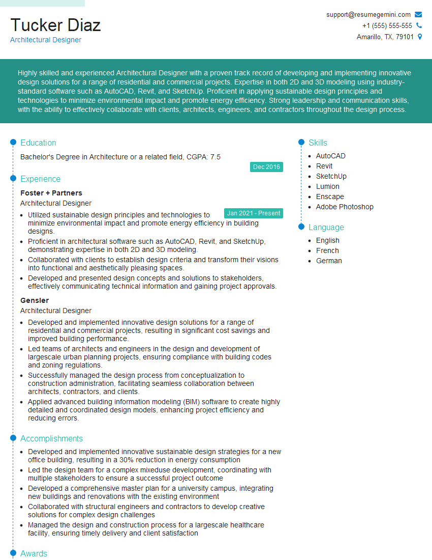
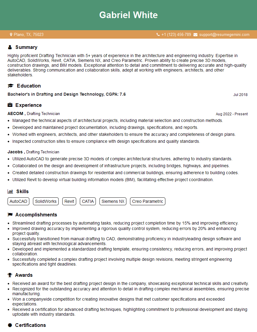
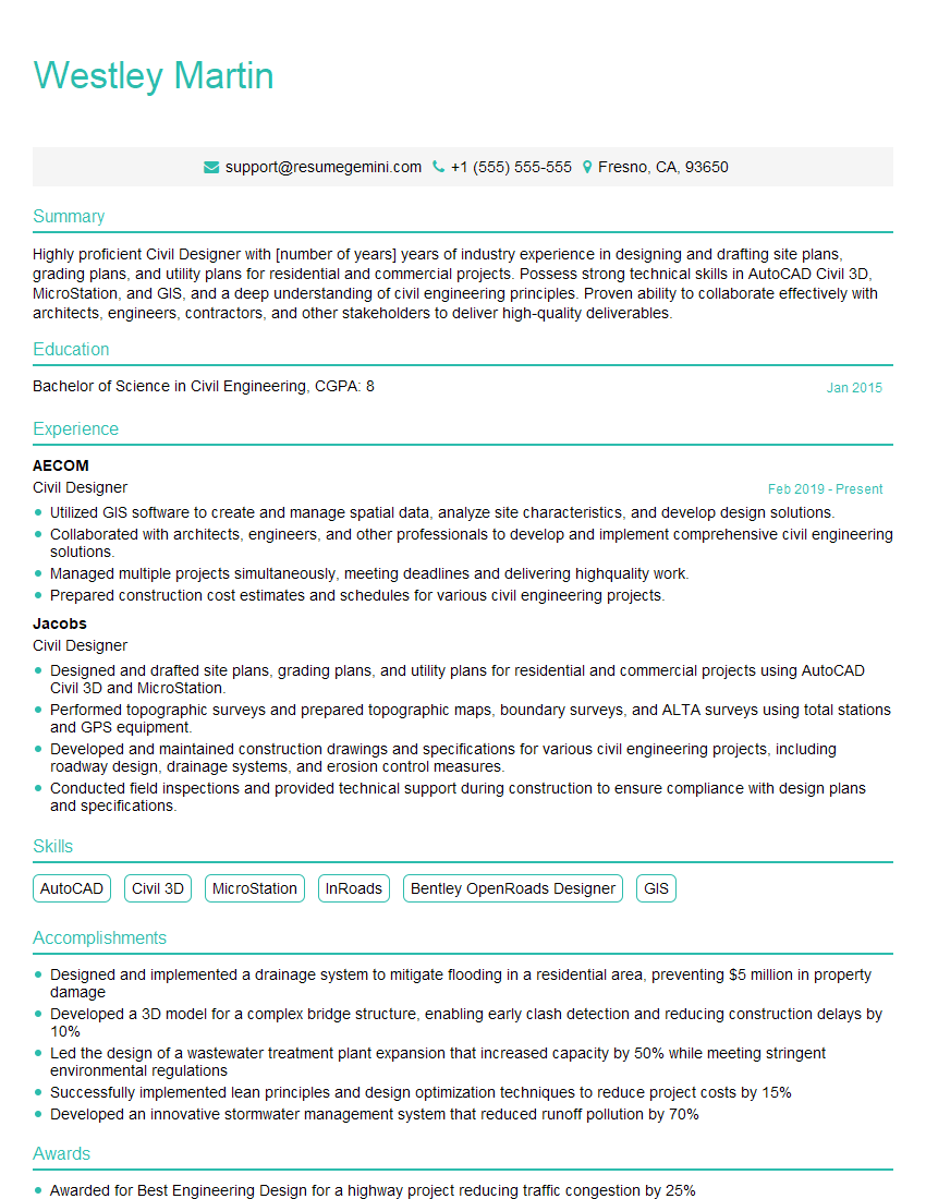
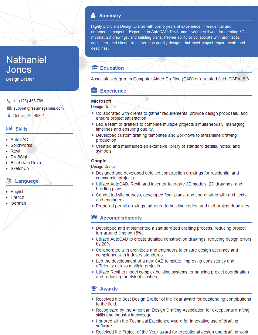
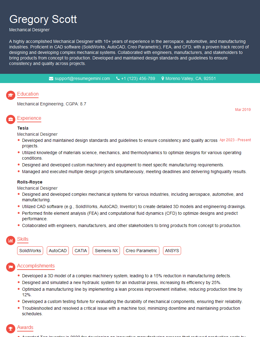
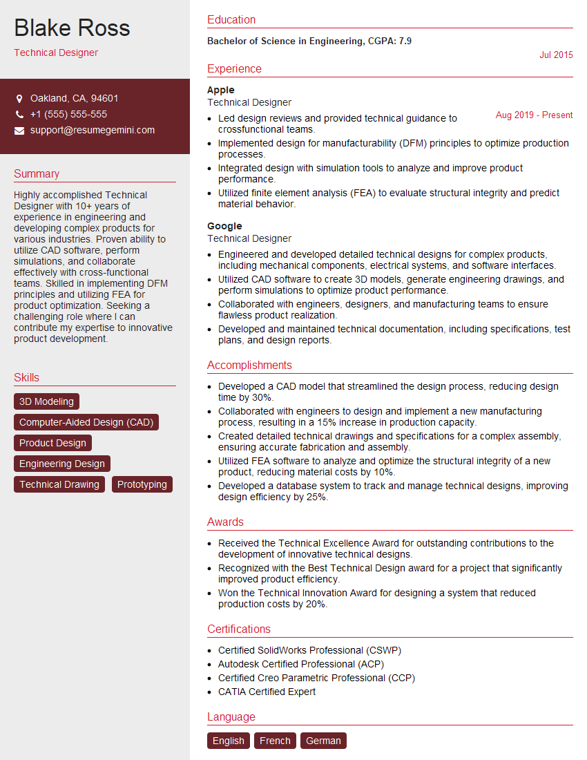
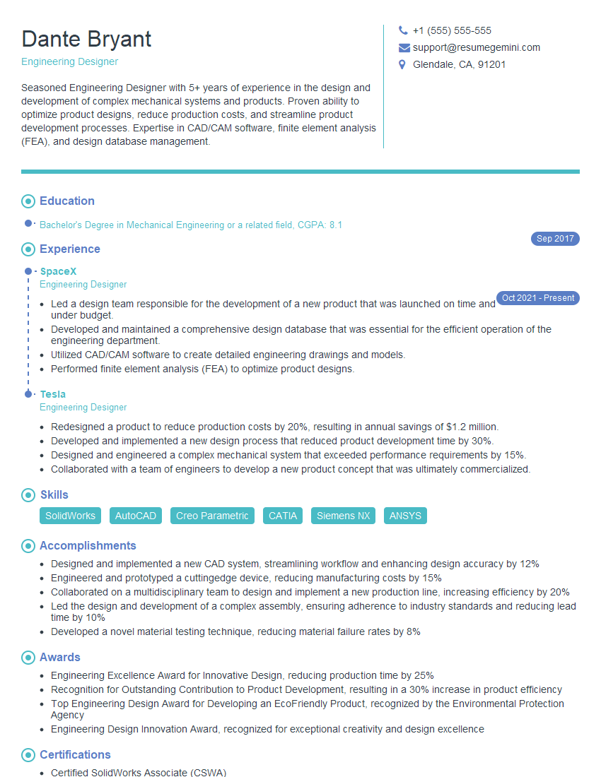
Mastering the use of engineering software and tools for creating and editing drawings and boxes is crucial for career advancement in many engineering fields. A strong command of these skills demonstrates your technical proficiency and problem-solving abilities, making you a highly valuable asset to any team. To maximize your job prospects, focus on creating an ATS-friendly resume that effectively highlights these skills. ResumeGemini is a trusted resource that can help you build a professional and impactful resume tailored to your specific experience. Examples of resumes tailored to showcasing expertise in Use engineering software and tools to create and edit drawings and boxes are available to help guide you.
Explore more articles
Users Rating of Our Blogs
Share Your Experience
We value your feedback! Please rate our content and share your thoughts (optional).
What Readers Say About Our Blog
Hi, I represent a social media marketing agency that creates 15 engaging posts per month for businesses like yours. Our clients typically see a 40-60% increase in followers and engagement for just $199/month. Would you be interested?”
Hi, I represent an SEO company that specialises in getting you AI citations and higher rankings on Google. I’d like to offer you a 100% free SEO audit for your website. Would you be interested?

