Are you ready to stand out in your next interview? Understanding and preparing for Advanced AutoCAD interview questions is a game-changer. In this blog, we’ve compiled key questions and expert advice to help you showcase your skills with confidence and precision. Let’s get started on your journey to acing the interview.
Questions Asked in Advanced AutoCAD Interview
Q 1. Explain your experience with AutoCAD’s dynamic input.
AutoCAD’s Dynamic Input is a powerful feature that allows you to enter commands and coordinates directly on the screen, eliminating the need to constantly switch between the command line and the drawing area. Think of it as a heads-up display for your commands. Instead of typing coordinates in the command line after selecting a command, you can simply click on the desired location and the coordinates automatically appear near your cursor. You can also directly input values (e.g., length, angle) while creating geometry. This significantly speeds up the drawing process and reduces errors.
For instance, when drawing a line, instead of typing LINE, then @10,5, you can simply select the start point, then move your cursor to the desired endpoint, and the distance and angle will be displayed dynamically. You can directly modify these values if needed. I routinely use Dynamic Input for precise and efficient drawing, particularly when working on detailed architectural or mechanical designs requiring multiple points and precise dimensions. The ability to instantly see the values and adjust them in real-time is invaluable.
Moreover, Dynamic Input offers a range of customization options. You can choose to display different coordinate systems (Cartesian, polar), modify the location of the input box, and even toggle individual features on or off based on your preferences. This degree of customization allows me to tailor the interface perfectly to my workflow.
Q 2. Describe your proficiency in creating and managing layers.
Layer management is fundamental to organizing and controlling the complexity of any AutoCAD drawing. Think of layers as stacked transparent sheets where each sheet contains different elements of your drawing. Proper layer management is crucial for clarity, efficiency, and error prevention. I typically organize my layers by object type (e.g., walls, doors, windows), discipline (e.g., architecture, MEP), or even by specific project phases. This approach ensures that my drawings remain clear and manageable, even with thousands of objects.
I use descriptive layer names that clearly indicate the content, such as Arch-Walls-Exterior or MEP-Plumbing-Pipes, and employ a consistent naming convention to maintain order. I also make use of layer properties, such as color, linetype, and lineweight, to further enhance visual clarity and differentiation between layer elements. For instance, all structural elements might be assigned a specific color and linetype to easily distinguish them from architectural features.
Beyond naming and properties, I leverage AutoCAD’s layer controls for managing layer visibility and plotting properties. I frequently freeze and thaw layers to improve performance and to selectively display specific parts of the drawing depending on the task at hand. This is especially helpful when working on large projects with numerous layers. Effective layer management saves considerable time and effort in the long run, greatly improving drawing comprehension and overall project management.
Q 3. How do you manage large and complex AutoCAD drawings efficiently?
Managing large and complex AutoCAD drawings requires a structured approach and the effective use of various features. Imagine trying to navigate a massive city without a map – it would be chaotic. Similarly, a disorganized AutoCAD drawing can be extremely challenging to work with. To maintain efficiency, I adhere to a multi-pronged strategy:
- Layer Management (as detailed above): This is the cornerstone of my approach. Logical layer organization significantly reduces clutter and improves performance.
- External Referencing (XREFs): For projects with multiple disciplines or large repeated components, I use XREFs to link external drawings. This prevents data redundancy and simplifies updates, as changes in the referenced files automatically propagate to the main drawing.
- Blocks and Attributes: Standardizing components into blocks with attributes (detailed in a later answer) eliminates repetitive work and ensures consistency throughout the project.
- Purge and Audit: Regularly running the
PURGEcommand removes unused objects, improving file size and performance. TheAUDITcommand detects and repairs errors in the drawing file, preventing unexpected crashes or data corruption. - Working Sets: This incredibly useful feature allows you to create simplified views of a complex drawing, focusing only on relevant parts. It drastically reduces the time needed to work on specific sections without the performance overhead of working with the entire drawing at once.
By combining these techniques, I ensure that even the most complex drawings remain manageable and efficient.
Q 4. Explain your experience with AutoCAD’s external referencing (XREFs).
External Referencing (XREFs) is a vital tool for managing large and collaborative projects. Imagine working on a building design where the structural, architectural, and MEP plans are separate but need to be integrated. XREFs allow you to seamlessly incorporate these separate drawings into a single master drawing without merging them permanently. This allows multiple individuals to work simultaneously on different aspects of a design. Any changes made to the XREF file are automatically reflected in the master drawing the next time it’s opened, assuming the XREF is set to ‘reload’ on opening.
I utilize XREFs extensively to manage large and complex projects. For instance, I might have a master drawing representing the overall site plan, with separate XREFs for individual building designs, landscape plans, and utility details. This keeps each aspect of the project manageable while allowing for a unified view when needed. I also utilize the XREF manager to manage the various referenced files, including their paths, status, and the option to override certain settings within the referenced file if necessary. The ability to control the visibility and the level of modification allowed within an XREF is an essential part of my workflow. For example, I might choose to only display certain layers from an XREF, and prevent any editing to that particular referenced file.
Q 5. How do you utilize blocks and attributes effectively in your workflow?
Blocks and attributes are crucial for improving efficiency and consistency in AutoCAD. Blocks are essentially reusable components – think of them as pre-fabricated parts. Once a component, like a door or window, is created as a block, it can be inserted multiple times throughout the drawing without having to recreate it each time. Attributes are data fields embedded within a block, allowing you to add information like size, material, or manufacturer to each instance.
For example, I might create a block for a standard door, including attributes for the door’s width, height, and material. When I insert this block into my drawing, I can easily populate the attributes with the specific details for each door. This ensures consistency in the design and simplifies the process of creating detailed schedules and reports. I would also save these blocks into my drawing template file to ensure they are consistently available to me in all projects. This method reduces drawing time, eliminates errors, and simplifies data management, particularly beneficial for projects with numerous recurring components.
Beyond simple components, blocks can incorporate complex assemblies. I frequently use blocks to represent entire building modules or sections, reducing the drawing complexity and improving performance. The ability to easily update attributes associated with a block is crucial for dynamic updating and schedule generation. It enables modifications to be done to a single block, and have those changes immediately updated across the entire drawing.
Q 6. Describe your experience with creating and using custom linetypes and text styles.
Custom linetypes and text styles allow for greater control over the visual presentation of AutoCAD drawings and enhance the overall professionalism of final outputs. Linetypes define the appearance of lines (e.g., dashed, dotted, center lines) and text styles control font type, size, and other text properties. Creating custom options lets you tailor the drawing’s aesthetic to project specifications and personal preferences.
For instance, I’ve created custom linetypes to represent different types of piping in a plumbing design, such as dashed lines for drainage pipes and solid lines for water supply. Similarly, I frequently develop specific text styles for different annotation needs. This might involve creating a style for dimensions, another for notes, and a third for titles, each with unique font size, height, and justification. These custom styles are saved within the drawing template so that they are available in every new drawing.
The process of creating a custom linetype involves specifying the dash, dot, and space lengths in a specific pattern. Similarly, creating custom text styles involves selecting fonts, adjusting heights, and configuring spacing and justification settings. By creating and using these custom options, I ensure visual consistency and clarity, improving the readability and professionalism of the finished drawings. These customization features allows for a unique look that reflect the requirements and style preferences of a project, greatly enhancing the end product.
Q 7. Explain your experience with AutoCAD’s plotting and printing features.
AutoCAD’s plotting and printing features are critical for generating high-quality output for presentations, construction, and client deliverables. The process goes beyond simply clicking ‘print’. It involves careful consideration of plot settings, such as paper size, scale, plot style, and printer configuration, to ensure that the output accurately and clearly represents the design intent.
I regularly utilize the Plot dialog box to precisely control these settings. I select the appropriate plotter or printer based on the output requirements, selecting the correct paper size to match the project’s needs. I meticulously manage the plot scale to guarantee that the drawing is reproduced at the intended size, ensuring all dimensions and annotations are clear and legible on the printed output. Plot styles, which are essentially sets of settings that define how objects will be rendered on the printed page, are crucial for creating distinct output optimized for either monochrome or color printing, or for managing line weights and line styles within the printed drawing.
Moreover, I routinely utilize named plot configurations (plot style table and page setup) to maintain consistency and efficiency across multiple drawings within a project. This standardized approach ensures that the same plot settings are readily accessible, saving valuable time and reducing errors. Managing these settings effectively is crucial for delivering professional and accurate printed documents that perfectly convey the design.
Q 8. How do you handle version control in AutoCAD projects?
Version control in AutoCAD projects is crucial for managing revisions, collaboration, and preventing data loss. Think of it like tracking changes in a Google Doc, but for complex designs. I typically employ a combination of strategies:
- AutoCAD’s built-in XREF functionality: External References (XREFs) allow linking separate drawings together. Changes in one drawing automatically update in linked drawings, making collaboration seamless and reducing file bloat. For example, if I have a master site plan and detailed drawings of individual buildings, the buildings can be XREFed into the site plan. Any updates to a building drawing instantly reflect in the site plan.
- Cloud-based solutions like Autodesk Docs or BIM 360: These platforms provide centralized storage, version history, and collaborative features. It’s like a shared Dropbox, specifically designed for CAD projects, allowing multiple users to access and modify files simultaneously while tracking all changes. This prevents conflicts and allows for easy rollback to previous versions if needed.
- Local file versioning: Before major changes, I always save the file with a descriptive name (e.g., ‘drawing_v2_revised_sections’). This creates a backup in case something goes wrong. This is especially helpful when working offline or with less robust cloud solutions.
By using a multi-layered approach combining XREFs, cloud services, and local file backups, I ensure efficient and safe version control in all my projects.
Q 9. Describe your experience with scripting or automation in AutoCAD (e.g., LISP, VBA, Dynamo).
Automating tasks in AutoCAD is essential for increasing efficiency and reducing errors. I’m proficient in both LISP and Dynamo, each with its strengths.
- LISP (Lisp programming language): LISP is a powerful, lower-level language. I’ve used it to create custom commands for repetitive tasks, such as automatically generating dimensions or creating complex geometric patterns. For example, I created a LISP routine to automatically generate title blocks with project-specific information, saving considerable time on each project. A simple example shows how to create a point at coordinates (10, 10):
(command "_.point" 10 10) - Dynamo (Visual Programming): Dynamo is a visual scripting language which excels in complex automation and BIM integration. I’ve used it for tasks such as generating families of parts, automating design changes across multiple drawings, and creating complex geometry based on parameters. Its visual nature allows for better collaboration and debugging than raw code. For example, I used Dynamo to automate the creation of a series of parametrically-defined building components based on pre-defined parameters, saving weeks of manual work.
The choice between LISP and Dynamo depends on the complexity and type of automation needed. LISP is ideal for smaller, more specific tasks while Dynamo shines when tackling larger, more complex projects.
Q 10. Explain your understanding of coordinate systems and transformations in AutoCAD.
Understanding coordinate systems and transformations is fundamental in AutoCAD. Imagine building with LEGOs – you need to know where each brick goes relative to others.
- World Coordinate System (WCS): The default coordinate system. It’s the overall reference point for everything in the drawing. Think of it as the ground plane of your project.
- User Coordinate System (UCS): You can create custom coordinate systems for easier work within specific areas. It’s like tilting the LEGO baseplate to work on a specific section of the model more easily.
- Transformations: These are operations like moving, rotating, scaling, and mirroring objects. It’s like manipulating your LEGO creations – moving a car, rotating a tower, or scaling a minifigure.
Understanding how to navigate and manipulate these systems is critical for accurate modeling and precise placement of objects. For instance, when designing a building, I’d frequently use UCS to define individual floors, which simplifies drawing details and greatly improves accuracy.
Q 11. How familiar are you with AutoCAD’s 3D modeling capabilities?
AutoCAD offers robust 3D modeling capabilities that go far beyond basic extrusion. I’m highly proficient in a wide range of 3D modeling techniques including:
- Solid Modeling: Creating 3D objects from solids – like creating a cube and then subtracting or adding other shapes.
- Surface Modeling: Creating 3D objects from surfaces – more flexible but can be complex.
- Mesh Modeling: Creating 3D objects from a collection of polygons or faces – ideal for organic shapes and complex geometries.
I frequently use these techniques in architectural, mechanical, and product design projects. For example, I’ve created detailed 3D models of entire buildings, including MEP (Mechanical, Electrical, and Plumbing) systems, using solid and surface modeling techniques. The ability to seamlessly integrate 2D and 3D models is also a key part of my workflow.
Q 12. Describe your experience with surface modeling in AutoCAD.
Surface modeling in AutoCAD is about creating 3D objects defined by their surfaces, rather than solids. This is particularly useful for organic shapes and complex geometries that are difficult or impossible to create with solid modeling. Think of sculpting with clay versus building with blocks.
- Surface creation methods: I’m experienced in creating surfaces through various methods like ruled surfaces, revolved surfaces, tabulated surfaces, and edge surfaces.
- Surface manipulation: I’m proficient in modifying surfaces using tools like blending, smoothing, and trimming.
- Surface analysis: I can use analysis tools to check the quality of the surfaces, such as curvature and continuity.
A practical example is designing a car body. The smooth curves and complex shapes of a car hood are easily modeled using surface modeling techniques, which would be incredibly difficult using only solid modeling.
Q 13. How do you utilize AutoCAD’s rendering capabilities?
AutoCAD’s rendering capabilities, though not as advanced as dedicated rendering software, are sufficient for creating visually appealing representations of 3D models. I typically utilize:
- AutoCAD’s built-in rendering tools: These provide a quick and easy way to generate basic renderings, perfect for quick visual checks.
- Third-party rendering engines: For high-quality photorealistic renderings, I often use third-party software such as V-Ray or Arnold, which integrate seamlessly with AutoCAD.
- Materials and lighting: I carefully select appropriate materials and lighting to enhance the visual appeal of the renderings, making sure the lighting is realistic and effectively highlights the design details.
In a recent project, I used V-Ray to render architectural models, producing high-quality images for presentations to clients, showcasing the proposed design effectively.
Q 14. Explain your experience with working with point clouds in AutoCAD.
Working with point clouds in AutoCAD is becoming increasingly common, especially in situations where 3D scanning is used for site surveys or as-built documentation. The process usually involves:
- Point cloud import: Importing point cloud data from various scanners (e.g., Leica, FARO) into AutoCAD.
- Point cloud manipulation: Cleaning the point cloud data – removing noise and outliers – and aligning it with the AutoCAD coordinate system.
- Point cloud utilization: Using the point cloud as a reference to create accurate 2D or 3D models. This is particularly valuable when working with existing structures for renovation or addition projects.
During a recent renovation project, I used point cloud data obtained from a 3D laser scanner to accurately model an existing building structure. This saved significant time and effort compared to traditional methods, resulting in a more precise model.
Q 15. Describe your experience with data extraction and reporting in AutoCAD.
Data extraction and reporting in AutoCAD are crucial for leveraging the design data for analysis and communication. I’ve extensively used various methods to achieve this, focusing on efficiency and accuracy. This includes using the DATAEXTRACTION command to pull specific data points from drawings, leveraging external databases like Excel via the EXPORT functionality, and using the powerful tools within AutoCAD to create custom reports. For example, I once worked on a large infrastructure project where I needed to generate a detailed report on pipe lengths and diameters for material procurement. I utilized the DATAEXTRACTION command to extract this information, and then used Excel to further analyze and present it in a clear, concise report with automated calculations of total length and cost. Another approach I often use involves creating custom attributes within the drawing, and then using the TABLE command to generate a summary report directly within the AutoCAD drawing itself, offering an integrated visualization of the key data points. This ensures that the report stays dynamically linked to the drawing, updating automatically with any revisions.
Career Expert Tips:
- Ace those interviews! Prepare effectively by reviewing the Top 50 Most Common Interview Questions on ResumeGemini.
- Navigate your job search with confidence! Explore a wide range of Career Tips on ResumeGemini. Learn about common challenges and recommendations to overcome them.
- Craft the perfect resume! Master the Art of Resume Writing with ResumeGemini’s guide. Showcase your unique qualifications and achievements effectively.
- Don’t miss out on holiday savings! Build your dream resume with ResumeGemini’s ATS optimized templates.
Q 16. How do you ensure drawing accuracy and quality control in your projects?
Ensuring drawing accuracy and quality control is paramount. My approach is multi-faceted. Firstly, I strictly adhere to established drafting standards and company best practices. This includes consistent layer management, proper naming conventions, and detailed annotations. Secondly, I employ rigorous self-checking techniques before any submission, meticulously reviewing dimensions, alignments, and adherence to specifications. Think of it like proofreading a crucial document – a single error can have cascading effects. I utilize AutoCAD’s powerful tools, including the MEASURE command for precise distance verification, and the AREA command for accurate area calculations. I also leverage the AUDIT command to identify and fix any potential inconsistencies or errors within the drawing. Furthermore, I use external quality control software to perform comprehensive checks, automating much of this validation process. In one project involving complex MEP designs, a rigorous process using such external software saved the project team from a potentially costly error in the layout of critical ductwork discovered during the automated validation.
Q 17. Explain your experience with collaborating with others on AutoCAD projects.
Collaboration is key in any design project. My experience in collaborative AutoCAD projects involves leveraging several approaches to ensure seamless teamwork. We heavily utilize cloud-based collaboration features within AutoCAD, allowing multiple users to work on the same drawing simultaneously without version conflicts. Regular team meetings are vital to discuss progress, address challenges, and synchronize efforts. Clear communication channels are maintained through project management software and regular updates. We also establish a shared style guide and drawing standards to guarantee consistency across the project. In one project designing a large-scale commercial building, we implemented a color-coded revision system where each team member had designated colors for their changes and additions. This made it incredibly easy to track progress, spot discrepancies, and ensure everyone worked from the latest approved versions. We also leveraged model-based collaboration, ensuring that updates were reviewed and approved before being incorporated into the central model.
Q 18. Describe your experience using AutoCAD with other design software (e.g., Revit, Civil 3D).
I possess significant experience integrating AutoCAD with other design software, primarily Revit and Civil 3D. The workflow typically involves exporting data from one platform and importing it into another. For example, I’ve often exported site survey data from Civil 3D into AutoCAD to create detailed site plans, utilizing the precision and flexibility of AutoCAD for intricate annotations. Similarly, I’ve imported 2D AutoCAD designs into Revit for 3D modeling and detailing. This interoperability minimizes data loss and maintains design consistency across different software. Understanding the strengths and limitations of each software is crucial for efficient workflows. AutoCAD excels at precision 2D drafting and detailed annotation, while Revit is superb for 3D modeling and BIM functionalities. By effectively combining these platforms, we can leverage the advantages of both. One specific instance involved creating site grading plans in Civil 3D and then exporting the contours and surfaces to AutoCAD to generate more detailed drawings for construction documents.
Q 19. How do you troubleshoot and resolve common AutoCAD issues?
Troubleshooting in AutoCAD involves a systematic approach. I first identify the nature of the problem: is it a rendering issue, a data corruption, a command error, or a system performance problem? I begin with basic troubleshooting steps such as restarting AutoCAD and verifying the system requirements are met. If the issue persists, I check the drawing for corrupted objects or blocks using the AUDIT and RECOVER commands. Online resources, including Autodesk’s support website and forums, are invaluable. I often search for error messages or symptoms to identify solutions. Sometimes, a simple fix is just resetting the settings or reinstalling a particular add-on. For more complex issues, I systematically isolate the problem by creating a new drawing and replicating steps to pinpoint the cause. In one situation, a complex drawing experienced significant slowdowns. By utilizing the PURGE command to remove unused objects and optimizing the layer structure, I improved performance significantly. Documentation and meticulous record-keeping are essential. I always try to document the steps taken, whether successful or not, as it helps during future troubleshooting and provides insights for more efficient solutions.
Q 20. Describe your experience with customizing the AutoCAD interface.
Customizing the AutoCAD interface is crucial for optimizing workflow and enhancing productivity. I extensively use the customization features to personalize tool palettes, create custom toolbars, and assign keyboard shortcuts. For example, frequently used commands get dedicated shortcuts, speeding up my work. I also create custom tool palettes for project-specific tools, like specialized symbols or blocks, making them readily accessible. This avoids searching through menus and improves efficiency. AutoCAD’s customizable menus allow tailoring the interface to individual preferences and project requirements. This might include creating a custom menu specifically for a particular type of drawing, such as electrical or architectural. Through effective customization, we can significantly reduce the time it takes to complete tasks, while ensuring consistency within and across projects.
Q 21. How do you stay up-to-date with the latest AutoCAD features and updates?
Staying up-to-date with the latest AutoCAD features and updates is crucial for maintaining proficiency and leveraging the software’s full potential. I subscribe to Autodesk’s official channels for notifications on new releases and updates. I actively participate in online forums, attending webinars, and engaging with online communities to learn about best practices and new features from fellow professionals and experts. I regularly explore the new functionalities in each release, especially focusing on features relevant to my areas of expertise. Hands-on practice with new features is key. I usually allocate time to experiment with new tools and commands, applying them to practice projects to solidify my understanding. Attending industry events and conferences offers invaluable opportunities to engage with the latest technological developments and network with peers, ensuring I am abreast of current industry standards and trends in CAD technology.
Q 22. Explain your understanding of AutoCAD’s object snaps and their use.
Object snaps in AutoCAD are incredibly helpful tools that allow you to precisely select points on existing objects when creating new geometry. Think of them as intelligent magnets, snapping your cursor to specific locations on objects rather than relying solely on visual estimation. This significantly improves accuracy and speeds up the drawing process.
For instance, instead of painstakingly trying to click on the exact midpoint of a line, you can use the MID object snap. Similarly, ENDPOINT snaps to the end of lines, INTERSECTION finds the point where objects cross, and CENTER locates the center point of circles or arcs. There are many more, each designed for a specific task.
- Endpoint: Snaps to the end of a line, arc, or other object.
- Midpoint: Snaps to the midpoint of a line, arc, or other object.
- Intersection: Snaps to the intersection point of two or more objects.
- Center: Snaps to the center point of a circle, arc, or ellipse.
- Quadrant: Snaps to the quadrant points of a circle or arc.
In a real-world scenario, imagine designing a building’s foundation. Using object snaps ensures that all walls meet precisely at their corners and that the foundation is perfectly centered on the plot, saving time and preventing costly errors down the line.
Q 23. How familiar are you with AutoCAD’s command line interface?
I’m extremely proficient with AutoCAD’s command line interface. I find it to be a powerful and efficient way to interact with the software, especially for repetitive tasks or complex operations. While the graphical user interface (GUI) is helpful for beginners, the command line offers a level of precision and control that is unmatched. It allows for rapid execution of commands and customization through options and system variables.
For example, instead of navigating through menus to draw a line, I can simply type LINE, enter the coordinates of the start and end points, and press Enter. This is significantly faster for experienced users. Further, commands often have shortcuts; L for LINE, C for CIRCLE, etc. This significantly accelerates the workflow.
My experience extends to utilizing command line options to fine-tune drawing parameters. For instance, I can use the -LAYER option with the LINE command to specify the layer for the new line directly, avoiding additional steps in the Properties Palette. Understanding the nuances of the command line and its options allows for a much more streamlined and efficient drafting process.
LINE 10,10 20,20 -LAYER MyLayerQ 24. Describe your experience with creating and managing design center libraries.
I have extensive experience creating and managing Design Center libraries. These libraries are invaluable for storing and reusing commonly used blocks, hatches, and other drawing components. This promotes consistency across projects and saves significant time and effort.
I’ve created libraries for everything from standard building components (doors, windows, fixtures) to custom-designed symbols and details. Organization within the library is key; I use a hierarchical structure with folders and subfolders to maintain clarity and easy navigation. This allows me to quickly locate and insert elements into my drawings, eliminating the need to recreate them repeatedly.
Beyond simply storing elements, I frequently utilize Design Center to share libraries among team members, ensuring consistency in our projects. This shared access facilitates collaborative work and maintains a standardized design language within the organization.
Properly maintaining and updating these libraries is crucial. I regularly review and purge obsolete or redundant elements to prevent clutter and maintain optimal performance. This involves version control to ensure that everyone is working with the most updated components.
Q 25. Explain your understanding of the concept of regeneration in AutoCAD.
Regeneration in AutoCAD is the process of redrawing the entire drawing on the screen. It occurs automatically whenever changes are made to the drawing, ensuring that the display reflects the current state of the model. This is essential for maintaining visual accuracy. However, very large and complex drawings can cause noticeable slowdowns during regeneration.
Think of it like refreshing a web page; when you make a change (add text, move an object), the page needs to redraw itself to show the changes. Similarly, in AutoCAD, regeneration updates the screen to display the latest changes. Understanding how regeneration works is critical for optimizing performance, especially with large drawings.
Several factors influence regeneration time, including the complexity of the drawing, the number of objects, and the system resources. Techniques to improve regeneration speed include purging unused blocks and layers, optimizing object properties, and using efficient drawing techniques.
For example, excessively complex blocks or numerous nested blocks can significantly increase regeneration times. Breaking down complex elements into simpler ones can dramatically improve performance.
Q 26. How do you handle drawing file organization and management?
Drawing file organization and management are paramount for efficiency and collaboration, especially in large projects. My approach involves a structured file system utilizing folders and subfolders based on project name, revision number, and drawing type. This allows for easy navigation and retrieval of specific drawings.
I consistently employ version control, typically using external tools such as cloud storage platforms or dedicated version control software. This helps track changes, revert to previous versions if needed, and collaborates effectively with team members, minimizing conflicts. Clearly numbered revisions (e.g., drawing_v01.dwg, drawing_v02.dwg) ensure traceability.
Furthermore, I utilize metadata, including keywords and descriptions, within each drawing file to enhance searchability and improve retrieval. This allows for rapid identification of specific drawings through keywords, project numbers, or other relevant identifiers.
Regular backups are crucial. I employ both local and cloud-based backups to safeguard against data loss. This multi-layered approach guarantees data recovery in case of hardware failure or accidental deletion.
Q 27. Describe your experience with using AutoCAD’s annotation tools effectively.
AutoCAD’s annotation tools are essential for creating clear and detailed drawings. My experience covers a broad range of these tools, from simple text and dimensions to more complex annotations like leaders, tables, and callouts. I consistently strive for clarity and precision to ensure effective communication within the drawing.
Effective annotation starts with a well-structured text style. Consistent fonts, sizes, and styles maintain a professional and easily readable output. I meticulously control dimension styles to ensure consistent representation of measurements, including precision, text height, and arrow styles. Proper layering and organization also play a crucial role in managing annotations, separating them from the model geometry for better clarity and management.
Advanced annotation techniques such as creating custom annotation scales, using dynamic blocks for dimensioning, and leveraging the power of tables for organizing complex information are integral to my approach. For example, a detailed plan may require a table to list materials or quantities. Automating these tasks through dynamic blocks ensures consistency and reduces errors.
I prioritize the readability of annotations. This includes using appropriate text sizes, avoiding text overlap, and strategically placing annotations so they don’t obscure important model elements. In a real-world context, imagine annotating a structural drawing. Clearly labeled dimensions and notes are essential for contractors to correctly understand and build the structure. Poorly placed or unclear annotations can lead to significant errors.
Q 28. Explain your approach to optimizing AutoCAD drawings for performance.
Optimizing AutoCAD drawings for performance is crucial for maintaining productivity, especially with large and complex projects. My approach to optimization involves a multi-pronged strategy addressing various aspects of the drawing file.
Firstly, I regularly purge unused items, including blocks, layers, and linetypes. This removes unnecessary data, reducing file size and improving regeneration speed. Secondly, I strive for efficient geometry. Overly complex geometry can negatively impact performance. Simplifying shapes where possible, avoiding unnecessary detail, and using appropriate object types can improve response times.
Xrefs (external references) should be managed effectively. Over-reliance on nested Xrefs can slow down regeneration. Careful planning and organization of Xrefs are important, possibly employing linked rather than attached Xrefs to optimize performance.
Regularly auditing the drawing for orphaned objects and removing them also dramatically improves performance. These are objects that no longer have any references, wasting resources.
Layer management is essential. Excessive layers or layers with overly complex properties can impact performance. I consolidate layers where possible, only creating new ones when necessary, and keep their properties lean and efficient.
Finally, regularly saving the drawing to compact the file size reduces unnecessary storage space and improves file handling performance.
Key Topics to Learn for Advanced AutoCAD Interview
- 3D Modeling Techniques: Mastering surface modeling, solid modeling, and mesh modeling techniques, including advanced commands and workflows for creating complex 3D geometries.
- Advanced Drafting and Annotation: Proficiency in creating detailed and accurate drawings, utilizing advanced annotation tools, dynamic blocks, and attributes for efficient documentation.
- Customization and Automation: Understanding and utilizing AutoLISP, VBA, or Dynamo to automate repetitive tasks, create custom tools, and enhance workflow efficiency. This demonstrates problem-solving skills and initiative.
- Data Extraction and Management: Experience with exporting data in various formats (DXF, DWG, etc.), managing large datasets, and utilizing external databases for improved project management.
- Parametric Design and Modeling: Deep understanding of constraints-based modeling, families, and parameters for creating flexible and adaptable designs, crucial for iterative design processes.
- Rendering and Visualization: Familiarity with rendering techniques within AutoCAD or through integration with other software to create high-quality visualizations for presentations and client communication.
- Collaboration and Teamwork: Experience with cloud-based collaboration tools and best practices for sharing and managing AutoCAD projects within a team environment.
- Problem-Solving and Troubleshooting: Demonstrate your ability to diagnose and resolve technical issues, optimize workflows, and provide efficient solutions to design challenges encountered in complex projects.
Next Steps
Mastering Advanced AutoCAD opens doors to exciting career opportunities in architecture, engineering, construction, and manufacturing, significantly increasing your earning potential and career trajectory. To maximize your job prospects, it’s crucial to present your skills effectively. Creating an ATS-friendly resume is key to getting your application noticed by recruiters. ResumeGemini is a trusted resource that can help you build a professional, impactful resume tailored to highlight your advanced AutoCAD expertise. Examples of resumes specifically designed for Advanced AutoCAD professionals are available to help guide you.
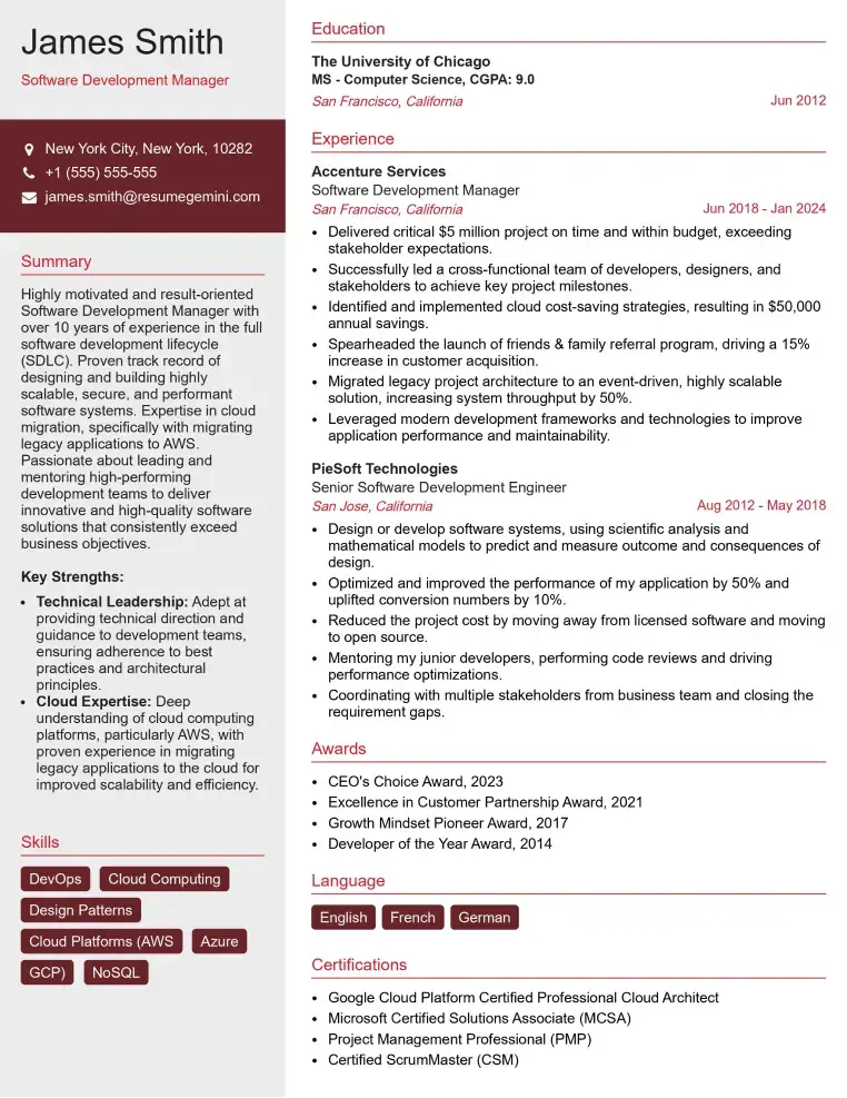
Check Out Resume Samples at ResumeGemini

Check Out Resume Samples at ResumeGemini
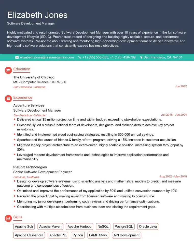
Check Out Resume Samples at ResumeGemini

Check Out Resume Samples at ResumeGemini
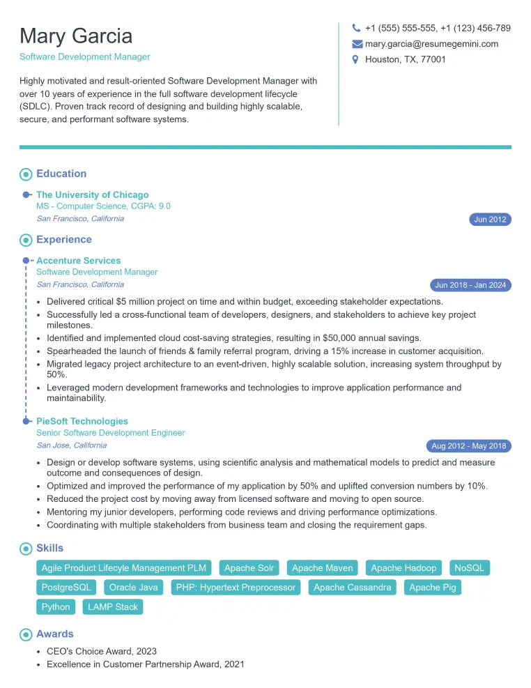
Check Out Resume Samples at ResumeGemini
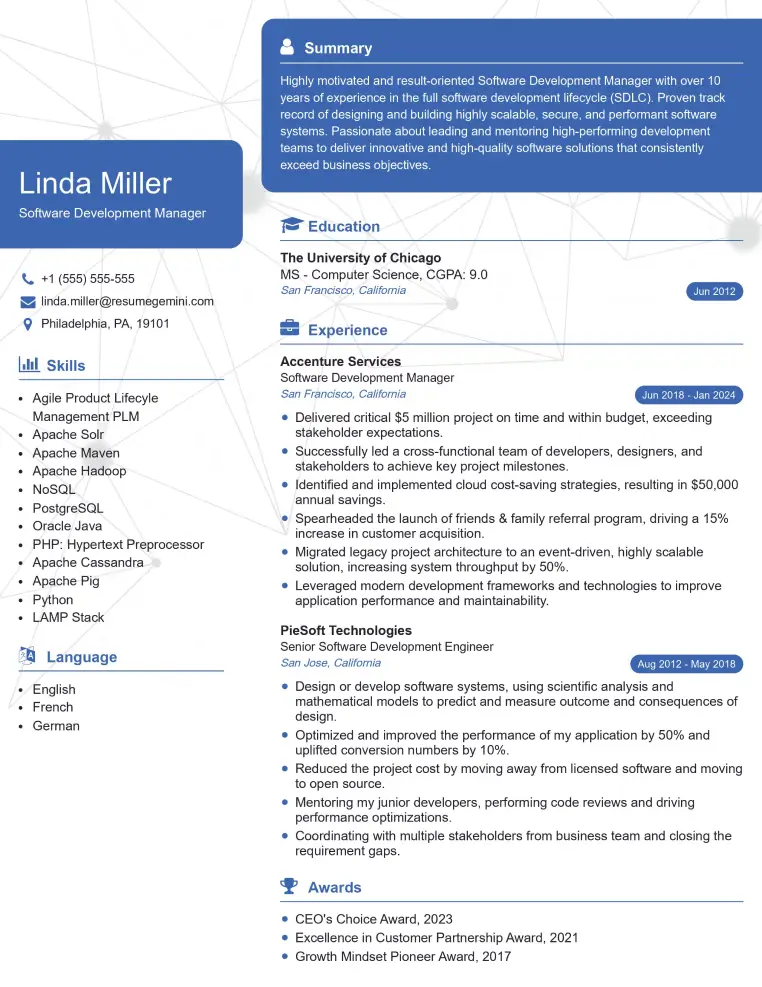
Check Out Resume Samples at ResumeGemini
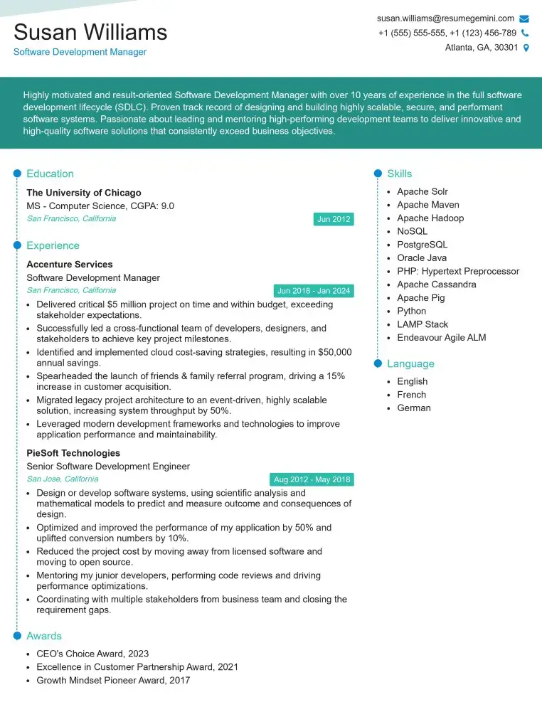
Check Out Resume Samples at ResumeGemini
Explore more articles
Users Rating of Our Blogs
Share Your Experience
We value your feedback! Please rate our content and share your thoughts (optional).
What Readers Say About Our Blog
Amazing blog
Interesting Article, I liked the depth of knowledge you’ve shared.
Helpful, thanks for sharing.