Are you ready to stand out in your next interview? Understanding and preparing for Electrical Print Reading and Interpretation interview questions is a game-changer. In this blog, we’ve compiled key questions and expert advice to help you showcase your skills with confidence and precision. Let’s get started on your journey to acing the interview.
Questions Asked in Electrical Print Reading and Interpretation Interview
Q 1. Explain the difference between a schematic diagram and a wiring diagram.
Schematic diagrams and wiring diagrams both represent electrical systems, but they do so at different levels of abstraction. Think of it like an architect’s blueprint versus a construction worker’s detailed instructions.
A schematic diagram shows the functional relationships between components using standardized symbols. It’s a simplified representation focused on how the circuit works, not its physical layout. It’s primarily concerned with the flow of signals and power. For instance, a schematic might show a resistor connected between two points, indicating its role in the circuit, without specifying its exact physical location on a board.
A wiring diagram, conversely, depicts the physical layout of the components and the wiring connections. It details exactly where each component is placed and how the wires connect them. Imagine it as a precise map of the circuit’s physical structure. It’s crucial for assembly and troubleshooting of the physical system.
Example: Consider a simple light switch circuit. The schematic might show a power source, a switch, and a light bulb connected in series, showing the logical flow. The wiring diagram would show how the wires are routed from the power source, through the switch, to the light bulb, with specific wire colors and connection points.
Q 2. Identify common electrical symbols used in blueprints and explain their meaning.
Electrical symbols are a universal language for electricians and engineers. Understanding them is fundamental to reading blueprints. Here are some common symbols:
- Power Source: Often depicted as a circle with a plus (+) and minus (-) sign, representing the positive and negative terminals of a battery or power supply.
- Resistor: A zig-zag line, representing a component that restricts the flow of current.
- Capacitor: Two parallel lines, representing a component that stores electrical energy.
- Inductor: A coil of wire, often shown as a spiral, representing a component that stores energy in a magnetic field.
- Switch: Various symbols exist depending on the type of switch (SPST, SPDT, etc.), typically showing contacts that can be opened or closed.
- Ground: A triangle or a ground symbol (three short horizontal lines) indicating a connection to earth ground.
- Light Bulb: A circle with a cross inside, representing an incandescent light bulb.
- Fuse: A circle with a broken line inside, representing a safety device that protects against overcurrents.
The specific symbols and their meaning can vary slightly depending on the standard used (e.g., ANSI, IEC). However, the fundamental concept remains the same: each symbol represents a specific electrical component.
Q 3. How do you interpret a ladder logic diagram?
Ladder logic diagrams are used to program Programmable Logic Controllers (PLCs). They represent logic functions using a ladder-like structure with two vertical rails representing power supply and loads. Horizontal rungs represent control circuits.
Interpreting a ladder logic diagram involves tracing the flow of power from the left rail to the right. Each rung represents a condition that, if met, allows power to flow to the output on the right rail. These conditions are usually represented by contacts (normally open or normally closed), coils (outputs), and timers or counters.
Example: A simple rung with a normally open contact connected to a coil represents a basic ON/OFF control. If the contact is closed (condition met), the coil energizes, activating the output (e.g., turning on a motor). Multiple rungs can be combined to create complex logic sequences.
Understanding the logic gates (AND, OR, NOT) and how they’re represented in the diagram is crucial. Reading from left to right and top to bottom, you can understand how the inputs affect the outputs.
Q 4. Describe your experience with reading and interpreting electrical schematics.
Throughout my career, I’ve extensively worked with electrical schematics and blueprints across various industrial settings, including manufacturing plants and power distribution systems. I’ve read and interpreted schematics for both low-voltage control systems and high-voltage power distribution networks. This has involved analyzing complex systems involving motor control circuits, PLC programming, and safety interlocks.
One particularly challenging project involved troubleshooting a malfunctioning automated assembly line. By meticulously studying the electrical schematics, I was able to pinpoint a faulty sensor that was causing the production line to stop unexpectedly. This highlighted the critical role of schematic diagrams in diagnosing and resolving electrical issues.
My experience isn’t limited to just reading – I’ve also created and modified schematics using industry-standard software. This experience ensures I can understand the design intent behind a schematic, identify potential design flaws and even contribute to better design practices.
Q 5. How do you identify potential hazards or errors in an electrical drawing?
Identifying hazards and errors in electrical drawings requires careful attention to detail and a thorough understanding of electrical safety regulations. I look for several key things:
- Missing Grounding: Absence of proper grounding connections is a major safety hazard, as it can lead to electric shocks.
- Improper Wiring: Incorrect wire sizing, insulation, or routing can cause overheating, shorts, and fires.
- Overloaded Circuits: Circuits with excessive current draw can lead to overheating and potential fires. I would check the calculations related to ampacity.
- Lack of Safety Devices: Missing fuses, circuit breakers, or other safety devices indicates a significant safety risk.
- Conflicting Information: Inconsistent or conflicting information within the drawing itself (e.g., different wire sizes indicated in different sections).
- Missing or Incomplete Information: The drawing must be complete and understandable. Missing component details, unclear labeling, or incomplete legends can introduce confusion and safety risks.
Beyond these specific issues, I always check the drawing for compliance with relevant electrical codes and standards, such as NEC (National Electrical Code) or similar regional standards.
Q 6. Explain the process for troubleshooting an electrical circuit using a schematic diagram.
Troubleshooting an electrical circuit using a schematic diagram is a systematic process. Here’s a step-by-step approach:
- Gather Information: Understand the problem; what’s not working? What are the symptoms?
- Review the Schematic: Carefully examine the schematic diagram to identify the components involved in the malfunctioning circuit.
- Trace the Circuit: Follow the path of the current from the source to the affected component, carefully noting all connections and components.
- Check for Obvious Problems: Look for obvious issues like loose connections, burned components, or broken wires.
- Perform Tests: Use multimeters or other test equipment to measure voltage, current, and resistance at various points in the circuit, comparing the readings to the expected values.
- Isolate the Fault: Based on the test results, isolate the faulty component or connection.
- Repair or Replace: Repair the faulty component or replace it with a new one.
- Verify the Repair: After making the repair, test the circuit thoroughly to ensure it’s functioning correctly.
The schematic acts as a roadmap, guiding you through the circuit and helping you pinpoint the problem efficiently. Without a clear schematic, troubleshooting becomes significantly more complex and time-consuming.
Q 7. What software are you proficient in for reading and interpreting electrical drawings?
I am proficient in several software packages for reading and interpreting electrical drawings. My experience includes using AutoCAD Electrical, EPLAN Electric P8, and SolidWorks Electrical. I am also familiar with other CAD software capable of handling electrical schematics. Each of these tools offers various features such as symbol libraries, wire numbering, and automatic report generation which significantly enhance efficiency in managing and reviewing electrical documentation.
My proficiency extends beyond simple viewing; I can use these tools to annotate drawings, make minor revisions, and even create new schematics when required. This combination of software expertise and practical experience ensures I can effectively contribute to projects involving electrical system design and maintenance.
Q 8. How do you interpret a one-line diagram?
A one-line diagram (SLD) is a simplified representation of an electrical system, showing the main components and their connections. Think of it as a roadmap of your electrical system, but without all the intricate details. It’s used for quick overview and understanding of power flow.
Interpreting an SLD involves understanding the symbols used (transformers, generators, buses, breakers, etc.). You trace the flow of power from the source (generator or utility grid) to the loads (equipment or buildings). You look for key features like protective devices (circuit breakers, fuses), busbars (central points of connection), and the voltage levels.
For example, you might see a generator symbol connected to a transformer symbol, which is then connected to a busbar representing a substation. From the busbar, multiple lines branch out to represent feeders supplying power to different parts of a facility. The SLD doesn’t show wiring details; its focus is on the overall system architecture and power flow.
Q 9. How familiar are you with NEC codes and their application to electrical drawings?
I’m very familiar with the National Electrical Code (NEC) and its crucial role in electrical drawing review. The NEC provides safety standards and requirements that must be met in all electrical installations. When reviewing drawings, I meticulously check for compliance with relevant NEC articles.
For example, I verify proper grounding, sizing of conductors based on ampacity requirements, correct placement of overcurrent protection devices (OCPDs), and adherence to regulations for specific applications like hazardous locations or special occupancies. Failure to comply with the NEC can lead to safety hazards and legal issues.
My experience extends to referencing the most recent NEC editions and understanding the nuances of various articles to accurately assess the design’s compliance and identify potential violations or areas for improvement. This ensures the electrical system is designed and constructed safely and efficiently.
Q 10. Explain the importance of proper documentation when reviewing electrical prints.
Proper documentation is paramount when reviewing electrical prints; it’s the backbone of a safe and functional electrical system. Without it, ambiguity and errors can easily creep in, leading to costly rework, project delays, and potential safety risks.
Complete documentation includes revision logs tracking changes, detailed specifications, parts lists, manufacturer data sheets for equipment, and calculations supporting design choices (e.g., voltage drop, short circuit current). This allows for a thorough understanding of the design intent, simplifying interpretation and reducing the likelihood of misinterpretations.
Imagine a scenario where a cable size isn’t specified. This can cause confusion and potentially lead to the use of an incorrect size, potentially causing overheating or failure. Comprehensive documentation eliminates this ambiguity and ensures a consistent and accurate understanding of the system.
Q 11. Describe your experience using electrical symbols and annotation in drawings.
I have extensive experience utilizing a wide range of electrical symbols and annotations. My knowledge encompasses both industry standards (like IEEE and ANSI) and company-specific notations. I’m proficient in using Computer-Aided Design (CAD) software to create and modify electrical drawings, incorporating the correct symbols and annotations for clarity and precision.
Understanding symbols is crucial; for instance, knowing the difference between a motor starter symbol and a contactor symbol is essential for understanding the control scheme. Annotations are equally important for providing additional information, such as cable sizes, wire types, equipment specifications, and connection details.
In practice, I consistently ensure that all symbols and annotations are clear, unambiguous, and consistent throughout the drawings. This is vital for those who will be installing, maintaining, and troubleshooting the system, ensuring proper construction and future maintenance.
Q 12. How would you approach interpreting a complex electrical drawing with multiple layers?
Interpreting complex drawings with multiple layers requires a systematic approach. I start by understanding the overall system architecture using the one-line diagram, followed by a detailed layer-by-layer analysis. Each layer may represent a different aspect of the system (e.g., power distribution, control wiring, instrumentation).
I employ a layered approach, focusing on one layer at a time. I start with the base layer (often power distribution), then systematically move to subsequent layers, cross-referencing information between them. This helps to build a holistic understanding of the entire system. Proper use of cross-referencing and legend tables is essential for navigating this complexity.
Think of it like peeling an onion: you systematically remove each layer, gaining a clearer understanding of the underlying structure with each step. This prevents information overload and reduces the risk of overlooking crucial details.
Q 13. What is your experience with various types of electrical drawings (e.g., single-line, three-line, etc.)?
My experience encompasses various types of electrical drawings: single-line diagrams (SLDs), three-line diagrams, schematic diagrams, wiring diagrams, and panel schedules. Each serves a specific purpose.
- Single-line diagrams provide a high-level overview of the power system.
- Three-line diagrams show more detail, including the three phases of power.
- Schematic diagrams illustrate the functional relationships between components.
- Wiring diagrams show detailed physical connections.
- Panel schedules list the components within electrical panels.
The choice of drawing type depends on the specific needs of the project. A detailed wiring diagram would be crucial for installation, while a single-line diagram is more useful for initial design and system overview. I can effectively interpret and utilize all these types of drawings.
Q 14. How do you handle discrepancies or inconsistencies you find in electrical drawings?
Discrepancies and inconsistencies in electrical drawings are a significant concern; they can lead to safety hazards and project delays. My approach is systematic and thorough.
First, I carefully document the discrepancies, noting their location and nature. I then try to reconcile these differences using available documentation, like specifications, manufacturer data sheets, and other related drawings. If resolution isn’t possible through documentation, I initiate a collaborative process by contacting the design engineer to clarify the ambiguities.
If the inconsistencies present a safety risk, I flag them as critical and recommend a design review or correction before proceeding. My priority is to ensure a safe and functional electrical system, so I thoroughly investigate and resolve any discrepancies before implementation.
Q 15. Can you explain the relationship between electrical drawings and other construction documents?
Electrical drawings are intrinsically linked to other construction documents, forming a comprehensive blueprint for a project. They don’t exist in isolation; instead, they interact and complement information found in architectural, structural, mechanical, and plumbing drawings. Think of it like a well-orchestrated symphony – each section plays a vital role, and the success of the whole depends on their harmonious collaboration.
For example, the electrical drawings will show the placement of lighting fixtures. The architectural drawings will show the ceiling layout where those fixtures will be mounted, ensuring that electrical placement aligns with the architectural design. Similarly, the structural drawings indicate the location of supporting beams and columns, critical for ensuring that electrical conduits are routed correctly and safely. Any discrepancies between these drawings can lead to costly rework and delays.
- Coordination: Electrical drawings must be coordinated with other disciplines to avoid conflicts, such as running conduit through a structural support column.
- Referencing: Electrical drawings often reference other drawings using numbers or notations to pinpoint specific locations or details.
- Integration: Successful projects ensure seamless integration; the electrical system works harmoniously within the overall building design.
Career Expert Tips:
- Ace those interviews! Prepare effectively by reviewing the Top 50 Most Common Interview Questions on ResumeGemini.
- Navigate your job search with confidence! Explore a wide range of Career Tips on ResumeGemini. Learn about common challenges and recommendations to overcome them.
- Craft the perfect resume! Master the Art of Resume Writing with ResumeGemini’s guide. Showcase your unique qualifications and achievements effectively.
- Don’t miss out on holiday savings! Build your dream resume with ResumeGemini’s ATS optimized templates.
Q 16. Describe your process for verifying the accuracy of electrical drawings.
Verifying the accuracy of electrical drawings is a crucial step to avoid costly errors and safety hazards. My process involves a multi-step approach:
- Visual Inspection: A thorough visual check for inconsistencies, missing information, or conflicts with other disciplines’ drawings. This includes checking for correct symbols, dimensions, and component specifications.
- Cross-referencing: I meticulously compare the electrical drawings with other construction documents (architectural, structural, etc.) to ensure compatibility and avoid conflicts.
- Calculations: I perform calculations (e.g., voltage drop, load calculations) to confirm that the designed electrical system meets the required specifications and complies with relevant electrical codes.
- Code Compliance: I verify that all aspects of the design adhere to the latest electrical codes and regulations, ensuring safety and legal compliance.
- Software Checks: When possible, I leverage electrical design software to perform automated checks, identifying potential errors or inconsistencies that might be missed during a manual review.
- Field Verification (if applicable): When possible, I conduct on-site inspections to verify that the actual installation matches the drawings.
For example, I once identified a discrepancy between the conduit size shown in the drawings and the actual load calculation. This could have led to overheating had it not been caught during the review process.
Q 17. How would you communicate technical information from electrical drawings to non-technical personnel?
Communicating technical information from electrical drawings to non-technical personnel requires clear and concise language, avoiding jargon. I use several techniques:
- Visual Aids: I use simplified diagrams and annotated drawings, highlighting key aspects relevant to the non-technical audience. Often a picture speaks a thousand words.
- Analogies: I use everyday analogies to explain complex concepts. For instance, I might compare electrical current to water flowing through pipes.
- Plain Language: I avoid technical terms unless absolutely necessary. If I must use a technical term, I provide a simple explanation.
- Step-by-step Explanations: I break down complex processes into manageable steps, making the information easier to digest.
- Interactive Sessions: Where possible, I use interactive sessions or presentations to ensure understanding and address any questions immediately.
For example, when explaining a circuit breaker’s function to a building owner, I would avoid technical details and instead focus on its role in protecting the building’s electrical system from overloads and short circuits—a simple explanation focused on safety and functionality.
Q 18. How familiar are you with different types of electrical systems (e.g., AC, DC, three-phase)?
I am highly familiar with various electrical systems, including AC (Alternating Current), DC (Direct Current), and three-phase systems. I understand their characteristics, applications, and limitations.
- AC Systems: I’m proficient in understanding single-phase and three-phase AC systems, including their voltage levels and power distribution capabilities. I understand the use of transformers, power factor correction, and harmonic analysis.
- DC Systems: I’m knowledgeable about various DC systems, including their application in low-voltage control circuits, battery backup systems, and specialized industrial equipment.
- Three-phase Systems: I understand the advantages of three-phase systems in power distribution and the different configurations (e.g., delta and wye). I can perform calculations related to three-phase power and motor control.
My experience spans various applications, from residential wiring to large-scale industrial installations. This allows me to adapt my approach depending on the specific project requirements.
Q 19. What are your skills in identifying and interpreting electrical components within drawings?
Identifying and interpreting electrical components within drawings is a fundamental skill for me. I am proficient in recognizing various symbols and understanding their meaning according to industry standards like ANSI and IEEE. This includes:
- Circuit Breakers: I can identify different types (e.g., molded case, air circuit breakers) and understand their ratings and functions.
- Transformers: I can interpret transformer specifications (e.g., voltage ratios, kVA ratings) and understand their role in voltage transformation.
- Motors: I can identify different motor types (e.g., AC induction, DC motors) and understand their specifications (e.g., horsepower, speed, voltage).
- Conductors and Cables: I can differentiate between different types of conductors (e.g., copper, aluminum) and cable constructions based on their symbols and specifications.
- Protective Devices: I can identify various protective devices (e.g., fuses, ground fault circuit interrupters) and understand their purpose.
I can quickly decipher the information conveyed through line diagrams, schematics, and panel layouts, understanding component interconnections and their operational sequences.
Q 20. Explain your experience with using electrical prints in the field during installation or maintenance.
I have extensive experience using electrical prints in the field during installation and maintenance. This hands-on experience is invaluable in bridging the gap between theoretical design and practical implementation.
On several occasions, I’ve used the prints to locate specific circuits or components during troubleshooting, which saved considerable time and effort. For instance, during a recent maintenance project, the electrical prints helped me quickly identify the faulty component in a complex industrial control system. This prevented a significant production downtime.
The process involves comparing the drawings with the actual installation, identifying any discrepancies, and resolving conflicts on site. This ensures that the work is done correctly and according to the design specifications.
Q 21. How do you utilize electrical drawings during the commissioning process?
Electrical drawings are crucial during the commissioning process, ensuring that the installed electrical system meets the design specifications and performs as intended. My role involves:
- Verification: I use the drawings to verify that the installed equipment matches the design, including the type, rating, and connection details.
- Testing: I refer to the drawings to conduct proper testing procedures, ensuring that all circuits and components are functioning correctly.
- Troubleshooting: The drawings are invaluable for troubleshooting any issues that may arise during the testing phase. They guide the process of identifying and resolving problems.
- Documentation: I use the drawings to document the completed system’s configuration and any deviations from the original design.
For example, during commissioning, I recently used the drawings to verify the correct wiring of a complex motor control center. This ensured that the motor operated safely and efficiently within its designed parameters. The drawings are our guide to a successful commissioning, ensuring a fully functional and safe system.
Q 22. Describe your ability to interpret and utilize conduit and cable schedules within electrical drawings.
Conduit and cable schedules are essential parts of electrical drawings, providing a detailed inventory of the wiring system. They act like a legend, linking the lines on the drawing to the actual physical components. Interpreting them involves understanding the symbology used and correlating it to the drawing. For example, a schedule might list “Conduit 1: 1-inch EMT, 200 ft,” alongside a specific conduit number shown on the drawing. Then, by referring to the cable schedule, I can determine what types and sizes of cables run within that conduit (e.g., “Cable 1: 3 #12 AWG THHN”). This allows me to understand the capacity of the conduit, the type of cable protection offered, and the current-carrying capacity of the circuit.
I utilize this information in several ways: First, during design review, I can verify that conduit sizing is appropriate for the number and size of cables. Second, during installation, I use the schedule as a checklist, ensuring all conduits and cables are correctly installed according to the plan. Third, during troubleshooting, the schedules provide critical information for tracing circuits and identifying potential problems. For example, if a circuit is malfunctioning, I can trace its number back to the schedule and determine the exact conduit and cable run, facilitating quick and efficient troubleshooting.
Q 23. How would you approach reviewing electrical drawings for compliance with safety regulations?
Reviewing electrical drawings for safety compliance is a crucial part of my process, and it involves a multi-step approach. First, I check for adherence to the National Electrical Code (NEC) and any applicable local codes. This includes verifying proper grounding and bonding techniques, adequate clearances around electrical components, the use of appropriate safety devices (GFCIs, AFCIs), and compliance with voltage and current ratings. I pay close attention to details such as proper labeling of circuits and equipment, ensuring that all safety-related information is clearly marked and accessible.
For example, I would check for proper grounding of metal enclosures, confirming that grounding wires are correctly sized and connected. I also look for correct overcurrent protection, ensuring that circuit breakers or fuses are sized appropriately for the connected load. I check for proper separation distances between energized conductors and equipment to prevent arcing and shorts, and that proper insulation types are used for the given environment. If any discrepancies are found, I would document them clearly and recommend appropriate corrective actions.
Q 24. How would you identify and resolve conflicts between multiple electrical drawings?
Conflicts between multiple electrical drawings are common and can lead to errors during construction or commissioning. My approach to resolving them is systematic. First, I identify the discrepancies. This may involve comparing panel schedules, wiring diagrams, and equipment layouts to find conflicting information about circuit numbers, wire sizes, or equipment locations. For example, one drawing might show a circuit connected to one panel, while another drawing shows the same circuit connected to a different panel.
Second, I determine the source of the conflict. This often requires researching revision history to determine which drawing is the most current and accurate. I’d consult with the designers or engineers to clarify the discrepancies, referring to project specifications and other relevant documentation. Third, I document the conflict resolution clearly. I update the drawings with the agreed-upon changes, ensuring that all affected drawings are consistent and that the revision history is correctly updated. Using revision control software and collaborating with other members of the team ensures a coordinated and efficient resolution process.
Q 25. Explain your experience with various drawing formats (e.g., PDF, DWG, DXF).
I’m proficient in various drawing formats, including PDF, DWG, and DXF. PDFs are commonly used for distributing final drawings and archiving, while DWG and DXF are native formats for AutoCAD and other CAD software that enable editing and modification. My experience with these formats includes not only viewing and interpreting them, but also using them for collaboration and review.
For instance, I can use the markup tools in PDF viewers to annotate drawings during reviews and identify areas needing clarification or correction. With DWG and DXF files, I can utilize CAD software to perform more sophisticated analyses, such as checking for clash detection or generating reports from the drawing data. Understanding the limitations of each format is important; for example, I am aware that PDFs are typically not suitable for detailed editing.
Q 26. How familiar are you with the process of creating and revising electrical drawings?
I possess extensive experience in both creating and revising electrical drawings using CAD software like AutoCAD Electrical. This includes creating schematic diagrams, panel layouts, and wiring diagrams. Creating a drawing starts with understanding the requirements of the project – collecting data on equipment, load calculations, and safety standards. Then, I use the CAD software’s libraries of symbols and components to create the drawings, carefully following standards and best practices for clarity and accuracy.
Revising drawings frequently involves incorporating changes based on field observations, design modifications, or corrections identified during review. I use version control software (such as Vault) and adhere to a consistent revision system to maintain accurate records of changes and ensure that all stakeholders are working with the most current version of the drawings. Proper documentation and revision control are crucial for preventing errors and ensuring project continuity.
Q 27. Describe your problem-solving skills related to interpreting ambiguous information on electrical drawings.
Ambiguous information on electrical drawings requires a systematic approach to problem-solving. First, I carefully examine the drawing itself for clues that might clarify the ambiguity. This could involve cross-referencing other drawings, checking symbols and legends, and identifying patterns in the design. Second, if the drawing remains unclear, I utilize my engineering judgment and experience to make informed assumptions while documenting these assumptions and indicating the areas of uncertainty. This might involve researching similar systems or consulting industry standards to determine the most probable interpretation.
For instance, if a drawing shows a conduit without specifying its size or contents, I might refer to other similar conduits in the drawing or project documentation to estimate the size and potential cable contents. I’d always document this assumption. Third, if the ambiguity cannot be resolved through these methods, I proactively seek clarification from the designer or engineer responsible for the drawing, rather than making potentially erroneous assumptions. Clear communication is essential to preventing errors and ensuring safety.
Q 28. How do you ensure the accuracy of information extracted from electrical drawings for use in reports or other documents?
Ensuring accuracy when extracting information from electrical drawings for reports or other documents is paramount. I follow a rigorous process: First, I carefully verify the information extracted from the drawing against other relevant project documents (specifications, schedules, etc.) to ensure consistency. Second, I use a methodical approach to data entry, implementing checks and double-checks to minimize errors. This might include using spreadsheets with cross-referencing and validation tools. Third, I maintain a detailed audit trail to track the source of all extracted data, allowing easy verification and correction in case of discrepancies.
For example, when generating a bill of materials from an electrical drawing, I would check quantities and specifications against the panel schedules and equipment lists. Any inconsistencies would be investigated and corrected. Clear documentation of my extraction process, including the version of the drawing used, helps ensure the reliability and traceability of the extracted information, crucial for project accountability and compliance.
Key Topics to Learn for Electrical Print Reading and Interpretation Interview
- Schematic Diagrams: Understanding the symbols, conventions, and their representation of electrical components and their interconnections. Practice interpreting complex schematics to trace circuits and identify potential issues.
- Wiring Diagrams: Interpreting wiring diagrams to understand the physical layout and connections of electrical systems. This includes identifying wire types, sizes, and routing.
- Blueprint Integration: Understanding how electrical schematics and diagrams relate to overall building or system blueprints. This includes locating electrical components within a larger architectural context.
- Electrical Codes and Standards: Familiarity with relevant electrical codes (e.g., NEC) and industry standards to ensure safe and compliant designs and installations. Be prepared to discuss common safety regulations.
- Troubleshooting and Problem Solving: Develop your ability to identify potential problems by analyzing schematics and diagrams. Practice explaining your troubleshooting methodology and problem-solving approach.
- Component Identification: Mastering the identification of various electrical components based on their symbols and specifications found within the drawings.
- One-Line Diagrams: Understanding and interpreting simplified representations of power systems, focusing on major components and power flow.
- PLC (Programmable Logic Controller) Diagrams: If applicable to your role, familiarize yourself with ladder logic diagrams and their interpretation in relation to automated systems.
Next Steps
Mastering Electrical Print Reading and Interpretation is crucial for career advancement in the electrical field. It demonstrates a strong foundational understanding of electrical systems and is highly sought after by employers. To maximize your job prospects, creating an ATS-friendly resume is essential. ResumeGemini is a trusted resource to help you build a professional and impactful resume that highlights your skills and experience. Examples of resumes tailored to Electrical Print Reading and Interpretation roles are available to help you craft the perfect application. Invest in your future—build a compelling resume that showcases your expertise.

Electrical Superintendent Resume Sample

Electrical Estimator Resume Sample

Automation Engineer Resume Sample
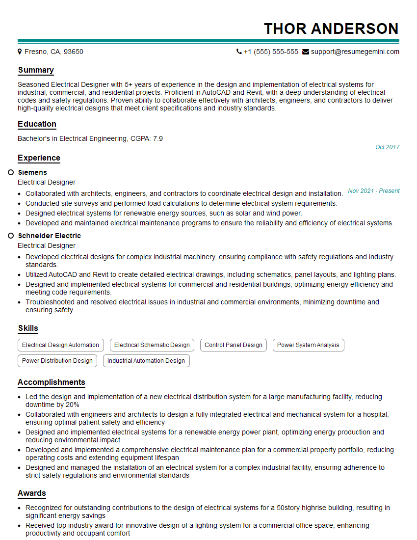
Electrical Designer Resume Sample

Electrical Engineer Resume Sample

Power Systems Engineer Resume Sample

Robotics Engineer Resume Sample

Electrical Drafter Resume Sample
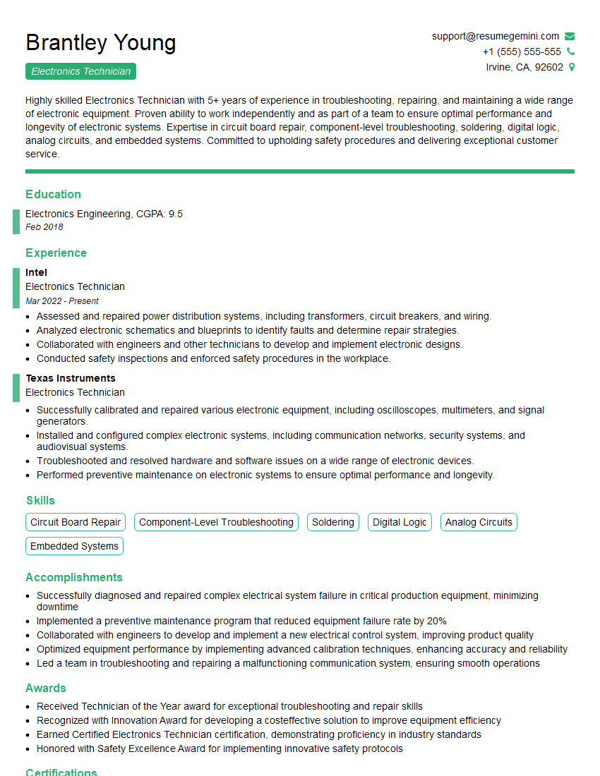
Electronics Technician Resume Sample
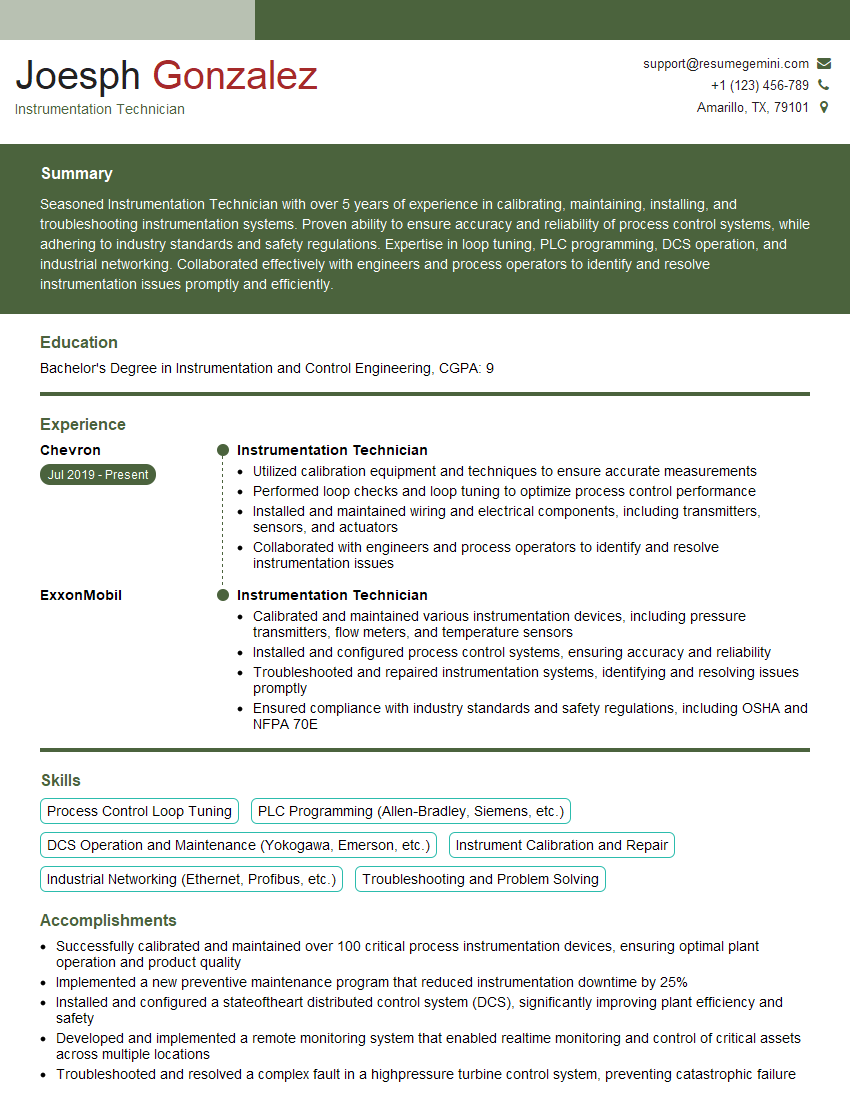
Instrumentation Technician Resume Sample
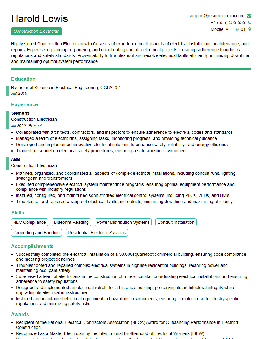
Construction Electrician Resume Sample
Electrician Resume Sample

Maintenance Electrician Resume Sample
Electrical Inspector Resume Sample
Control Systems Technician Resume Sample
- Electrical Superintendent
- Electrical Estimator
- Automation Engineer
- Electrical Designer
- Electrical Engineer
- Power Systems Engineer
- Robotics Engineer
- Electrical Drafter
- Electronics Technician
- Instrumentation Technician
- Construction Electrician
- Electrician
- Maintenance Electrician
- Electrical Inspector
- Control Systems Technician
Explore more articles
Users Rating of Our Blogs
Share Your Experience
We value your feedback! Please rate our content and share your thoughts (optional).
What Readers Say About Our Blog
Amazing blog
Interesting Article, I liked the depth of knowledge you’ve shared.
Helpful, thanks for sharing.