Unlock your full potential by mastering the most common Electrical System Simulation and Analysis interview questions. This blog offers a deep dive into the critical topics, ensuring you’re not only prepared to answer but to excel. With these insights, you’ll approach your interview with clarity and confidence.
Questions Asked in Electrical System Simulation and Analysis Interview
Q 1. Explain the difference between transient and steady-state analysis in electrical systems.
In electrical system analysis, we differentiate between transient and steady-state analyses based on how the system responds to changes. Steady-state analysis examines the system’s behavior after it has settled down, meaning all initial conditions have faded away and the system’s variables are no longer changing significantly. Think of it like a hot cup of coffee left on a table – eventually, it reaches room temperature and stays there. We’re interested in the final, stable operating point. Transient analysis, on the other hand, focuses on the system’s response during the period of change. It’s like watching that hot cup of coffee cool down; we’re interested in how the temperature changes over time until it reaches steady-state. Transient analysis is crucial for understanding short-term behavior, particularly during events like switching operations, faults, or sudden load changes.
For instance, in a power system, steady-state analysis might determine the voltage and current magnitudes under normal operating conditions. Transient analysis would be vital in determining the system’s response to a sudden three-phase fault, calculating the fault current, and predicting the impact on system stability.
Techniques like phasor analysis are commonly used for steady-state analysis, while numerical methods such as Euler’s method, Runge-Kutta methods, and trapezoidal rule are employed in transient analysis to solve differential equations describing the system’s dynamics.
Q 2. Describe your experience with various simulation software packages (e.g., PSIM, MATLAB/Simulink, PSCAD).
Throughout my career, I’ve extensively used several simulation software packages, each with its strengths and weaknesses. MATLAB/Simulink is my go-to for its versatile modeling capabilities, especially for complex control systems and signal processing. I’ve used it to model everything from motor drives to grid-connected inverters, leveraging its extensive toolboxes. For example, I designed a Simulink model to simulate the transient response of a grid-tied photovoltaic system during grid disturbances. The ability to easily integrate custom code and visualize results was incredibly beneficial.
PSIM has been instrumental in detailed power electronics circuit simulations. Its intuitive interface and built-in components significantly accelerate the modeling process. I recently used PSIM to analyze the efficiency and harmonic distortion of a resonant DC-DC converter design, iteratively optimizing the component values to meet performance specifications. The ease of creating waveforms and analyzing harmonic content within PSIM saved a considerable amount of time.
I also possess experience with PSCAD for simulating large-scale power systems, particularly during fault analysis and stability studies. Its emphasis on electromagnetic transients makes it invaluable for high-fidelity modeling of power system components. A notable project involved using PSCAD to simulate the impact of a large wind farm on a distribution network’s stability, assessing the influence of various protection schemes.
Q 3. How do you handle model validation and verification in your simulations?
Model validation and verification (V&V) are crucial steps to ensure simulation results are reliable. Verification confirms that the simulation model accurately represents the intended mathematical model. This involves checking the code for errors, ensuring correct implementation of equations, and using code verification techniques. For example, I’d perform unit testing on individual components or sub-models within the simulation to guarantee they function independently.
Validation, on the other hand, compares the simulation results against real-world data or experimental results. This requires access to measurement data from the real system or conducting experimental tests on a prototype. For instance, if simulating a motor drive, I would compare the simulated speed and torque responses to those measured experimentally under various operating conditions. Discrepancies highlight areas for model refinement, possibly needing adjustments to parameters, algorithms, or even the underlying model structure itself. Documenting the entire V&V process ensures transparency and traceability, building trust in the simulation’s findings.
Q 4. What are the common challenges encountered during electrical system simulation?
Several challenges commonly arise during electrical system simulations. One major hurdle is model complexity. Accurate representation often requires intricate models with numerous parameters, leading to increased computational burden and potentially longer simulation times. Another is handling nonlinearities present in many electrical components (e.g., saturation of transformers, diodes). These require advanced numerical techniques and careful consideration of convergence issues.
Data availability can also pose a problem. Validating simulations requires access to accurate real-world data, which might be limited, expensive to acquire, or insufficient to fully validate all aspects of the model. Furthermore, dealing with uncertainty in component parameters and environmental factors is a critical challenge. Employing robust design techniques and sensitivity analysis helps to mitigate this, allowing us to assess the impact of parameter variations on simulation results.
Finally, ensuring numerical stability and accuracy during simulation is paramount. The choice of numerical methods and appropriate step sizes significantly impact the quality of results. An unsuitable choice can lead to inaccurate, unstable, or even divergent results.
Q 5. Explain your understanding of different numerical methods used in electrical system simulation.
Various numerical methods are employed in electrical system simulation, each with its advantages and disadvantages. Explicit methods, like Euler’s method and Runge-Kutta methods, are relatively simple to implement, but they might require smaller time steps for stability, particularly for stiff systems. Implicit methods, such as the trapezoidal rule and backward Euler method, are more computationally expensive per step but allow for larger time steps, enhancing computational efficiency for stiff systems. Stiffness refers to the presence of widely varying time constants in the system.
Harmonic balance techniques are effective for analyzing systems operating under periodic steady-state conditions, particularly in power electronics applications. This method converts the time-domain equations into the frequency domain, simplifying the analysis of harmonic distortion and other frequency-related phenomena.
The choice of the numerical method depends on factors like the system’s stiffness, desired accuracy, and computational resources. For instance, an explicit method might suffice for a simple circuit, while an implicit method would be preferable for a large-scale power system exhibiting stiffness. Choosing the right method is a key aspect of ensuring accurate and efficient simulations.
Q 6. How do you choose appropriate simulation models for different applications?
Selecting appropriate simulation models depends heavily on the application’s requirements and the desired level of detail. For preliminary design studies or quick estimations, a simplified model might suffice. This might involve using idealized components and neglecting secondary effects. For example, a simplified model might be used to estimate the voltage regulation of a power transformer, neglecting core losses and saturation effects.
However, for detailed analysis or design optimization, a more sophisticated model incorporating nonlinearities, detailed component models, and external factors is needed. This is especially important for critical systems where accuracy is paramount. For instance, simulating a high-voltage direct current (HVDC) system would necessitate a detailed model that includes the converter control systems, cable parameters, and grid interaction.
The desired level of accuracy is a critical factor. High-fidelity models provide a more realistic representation but require more computational resources. The trade-off between accuracy, simulation time, and computational cost should always be carefully considered when selecting a simulation model.
Q 7. Describe your experience with simulating power electronic converters.
I have significant experience simulating power electronic converters using various software packages. My work has involved modeling a wide range of converters, including DC-DC converters (buck, boost, buck-boost, Cuk, etc.), AC-DC converters (rectifiers), DC-AC converters (inverters), and AC-AC converters (cycloconverters). The modeling process typically involves representing the switching behavior of the converter, the dynamics of the passive components, and the control system. Average-value models are often used for steady-state analysis and control design, while more detailed switching models are employed for transient analysis to accurately capture high-frequency switching effects.
For example, I’ve used Simulink and PSIM to design and simulate control algorithms for grid-tied inverters, focusing on aspects like voltage and current control, grid synchronization, and harmonic mitigation. One project focused on the development of a control strategy to minimize harmonic distortion injected into the grid by a large number of distributed inverters. The simulation allowed us to identify optimal control parameters and assess the impact of different control strategies on grid stability.
Accurate modeling of switching devices and their parasitic elements (like diode reverse recovery) is critical to obtaining realistic simulations of power electronics. Moreover, the inclusion of losses (conduction and switching) in the simulation is essential for assessing the converter’s efficiency.
Q 8. How do you handle uncertainty and noise in your simulations?
Uncertainty and noise are inherent in real-world electrical systems. In simulations, we handle them using several techniques. One common approach is to incorporate probabilistic models. Instead of using fixed values for parameters like resistance or capacitance, we use probability distributions (e.g., Gaussian, uniform) to represent their inherent variability. This allows us to run Monte Carlo simulations, where the simulation is repeated many times with different randomly sampled parameter values. The results then provide a statistical representation of the system’s behavior, including its sensitivity to parameter variations.
Another method involves using noise models directly within the simulation. For example, we might add white noise to represent thermal noise in a circuit or use more sophisticated models to simulate interference from external sources. The choice of noise model depends heavily on the specific application and the type of noise present. For instance, in power system simulations, we might model random fluctuations in load demand using time series analysis and stochastic processes.
Finally, robust control techniques can be integrated into the simulation to mitigate the effects of uncertainty and noise. These techniques are designed to ensure system stability and performance despite variations in parameters or the presence of disturbances.
Q 9. What are the limitations of electrical system simulation?
Electrical system simulations, while powerful, have several limitations. One significant limitation is the level of detail and accuracy that can be practically achieved. Complex systems often involve millions of components, leading to computationally expensive simulations and potential simplifications of certain components or phenomena. For example, capturing the precise electromagnetic interactions in a high-frequency circuit requires significantly more computational resources than simulating a low-frequency power system.
Another limitation stems from the inherent assumptions and approximations made in building the model. Simplifying assumptions, while necessary for manageable simulation times, can lead to inaccuracies. For instance, modeling a transmission line as a simple lumped element may be accurate at low frequencies, but may fail to capture higher-order effects at higher frequencies.
Finally, the simulation’s fidelity is only as good as the input data. Inaccurate or incomplete input data will inevitably lead to inaccurate simulation results. This emphasizes the crucial importance of careful data acquisition and validation before running any simulation.
Q 10. Explain your experience with real-time simulation.
My experience with real-time simulation includes working on projects involving hardware-in-the-loop (HIL) testing. In HIL testing, a real-time simulator interacts with a physical system or a piece of hardware under test. For example, I’ve worked on a project simulating the control system of a wind turbine, where the simulated wind conditions and grid response were fed into the control system’s hardware, while the hardware’s outputs were monitored by the simulator. This type of real-time simulation is invaluable for validating control algorithms, testing protection schemes, and identifying potential integration issues before deploying systems in the field.
The critical aspect of real-time simulation is ensuring that the simulation runs fast enough to keep up with the real-time response of the physical system. This often involves careful model simplification and the use of specialized real-time simulation software and hardware. I am proficient in using tools like Opal-RT and dSPACE for this purpose. Careful consideration of computational efficiency is crucial in these scenarios.
Q 11. How do you analyze simulation results to identify potential problems?
Analyzing simulation results involves a multi-step process. First, I visually inspect waveforms and key performance indicators (KPIs) to get a general overview of the system’s behavior. This can highlight obvious issues like excessive voltage drops, harmonic distortion, or instability. Next, I perform more rigorous quantitative analysis. This includes examining statistical measures like mean, standard deviation, and percentiles (particularly important for Monte Carlo simulations), calculating frequency spectrum analysis for harmonic content, and carrying out transient analysis to identify overshoots and oscillations.
For example, in power system analysis, I might investigate voltage sags and swells, calculate fault currents, and analyze system stability using eigenvalue analysis. To pinpoint the source of potential problems, I might use sensitivity analysis to determine which parameters have the largest impact on the KPIs. This allows for a targeted approach to design improvements and problem solving. Finally, generating reports and visualizations of the results using specialized software is a critical step in communicating the findings to stakeholders.
Q 12. Describe your experience with co-simulation techniques.
Co-simulation involves linking multiple simulation tools together to model different aspects of a system that would be difficult or impossible to simulate within a single tool. For instance, I’ve used co-simulation to model a power electronic converter integrated within a power system. The converter’s behavior might be simulated using a circuit simulator like PSIM or PLECS, while the power system is modeled using a dedicated power system simulator like PSS/E or PowerWorld.
Effective co-simulation relies on well-defined interfaces between the different simulators and careful consideration of data exchange formats and timing. The communication protocols, whether they’re based on standard interfaces or custom solutions, need to ensure accuracy and efficient data transfer. One needs to be mindful of potential numerical issues and synchronization challenges arising from the interaction between different solvers in different tools. Experience with tools like Functional Mock-up Interface (FMI) and co-simulation platforms is key to successful implementation.
Q 13. Explain your understanding of electromagnetic compatibility (EMC) simulation.
Electromagnetic compatibility (EMC) simulation focuses on predicting and mitigating electromagnetic interference (EMI) within a system. This is crucial in ensuring that a device or system operates correctly without causing or being susceptible to interference from other devices or the environment. EMC simulations typically involve analyzing the electromagnetic fields generated by different components and determining their impact on other parts of the system or on nearby devices.
Software tools like CST Studio Suite, ANSYS HFSS, and COMSOL are often used for these simulations. These tools employ numerical methods, such as the finite element method (FEM) or the method of moments (MoM), to solve Maxwell’s equations and determine the electromagnetic fields. The simulations can be used to optimize the design of components to reduce EMI emissions and improve immunity to interference. For instance, we might simulate the effects of shielding, grounding, and filtering techniques to improve EMC performance.
Q 14. How do you optimize simulation models for speed and accuracy?
Optimizing simulation models for both speed and accuracy is a constant balancing act. Several strategies can be employed. One approach is model order reduction (MOR). MOR techniques reduce the complexity of the model by approximating it with a smaller, lower-order model that preserves the key dynamic behavior. This significantly speeds up the simulation without substantial loss of accuracy. Another technique is to utilize different numerical integration methods. Implicit methods are typically more computationally expensive but can handle stiff systems more efficiently. Explicit methods are generally faster but may require smaller time steps for stability in stiff systems. The choice depends heavily on the specific system being simulated.
Furthermore, careful attention should be given to the choice of simulation parameters and solver settings. Using adaptive time steps and appropriate tolerances can lead to faster convergence and better efficiency. Parallel computing techniques can be utilized to speed up simulations further, especially when dealing with large-scale models. Finally, exploiting model symmetries and utilizing hierarchical modeling can enhance both the accuracy and efficiency of the simulation.
Q 15. What are your preferred methods for debugging simulation models?
Debugging simulation models is crucial for ensuring accuracy and reliability. My approach is systematic and involves a combination of techniques. First, I always start with a visual inspection of the model, checking for obvious errors in wiring diagrams, component parameters, and control logic. This is like meticulously checking a circuit board for loose wires before powering it up.
Next, I employ a divide-and-conquer strategy. If the overall simulation result is incorrect, I break down the model into smaller, manageable blocks and simulate each individually. This helps isolate the source of the error. For instance, if I’m simulating a power system, I might separately check the generator model, the transmission line model, and the load model.
Furthermore, I leverage the built-in debugging tools provided by the simulation software. Most simulation packages offer capabilities like waveform monitoring, step-by-step execution, and variable inspection. This allows me to track the values of key variables throughout the simulation and pinpoint where discrepancies arise. For example, I might use these tools to observe voltage and current waveforms at different points in a circuit to understand the behavior of a specific component.
Finally, I rely on print statements (or equivalent logging mechanisms) within the simulation code to track the values of critical variables at different stages. This provides granular insights into the simulation’s internal workings. Think of it as adding strategically placed indicators to a complex system to monitor its behavior.
Career Expert Tips:
- Ace those interviews! Prepare effectively by reviewing the Top 50 Most Common Interview Questions on ResumeGemini.
- Navigate your job search with confidence! Explore a wide range of Career Tips on ResumeGemini. Learn about common challenges and recommendations to overcome them.
- Craft the perfect resume! Master the Art of Resume Writing with ResumeGemini’s guide. Showcase your unique qualifications and achievements effectively.
- Don’t miss out on holiday savings! Build your dream resume with ResumeGemini’s ATS optimized templates.
Q 16. Describe your experience with hardware-in-the-loop (HIL) simulation.
Hardware-in-the-loop (HIL) simulation is a powerful technique that combines real-time simulation with physical hardware. I’ve extensively used HIL simulation for testing control systems in power electronics applications. For instance, in a recent project involving a grid-tied inverter, I used an HIL simulator to test the inverter’s control algorithm under various grid fault conditions. The real-time simulator created a virtual grid environment, while the actual inverter hardware was connected and subjected to simulated disturbances.
The beauty of HIL lies in the ability to test control strategies in a realistic environment without the risks associated with live hardware testing. For instance, we could simulate extreme grid faults and observe the inverter’s response without any danger of harming the hardware or the grid. This significantly reduces the cost and risks associated with real-world testing. The process typically involves a real-time simulator (often using FPGA or specialized software), an interface (connecting the simulator to the hardware), and the hardware under test (e.g., a power converter, a motor drive, or a protection relay).
In this particular project, we used dSPACE hardware and software, which provides comprehensive capabilities for HIL simulations in the power systems domain. The software allowed us to model the grid behavior accurately, including frequency variations, voltage dips, and three-phase faults. The results from the HIL tests helped us fine-tune the control algorithm and ensure robust performance under various operational conditions.
Q 17. Explain your understanding of different types of power system faults and how you simulate them.
Power system faults are categorized into various types, and accurately simulating them is essential for designing reliable and resilient systems. The common types include:
- Symmetrical Faults: These involve all three phases experiencing identical faults simultaneously, such as a three-phase short circuit. They are relatively simple to model.
- Unsymmetrical Faults: These are more complex and involve faults affecting only one or two phases. Examples include line-to-ground faults, line-to-line faults, and double line-to-ground faults. Modeling these often requires more detailed representations of the system’s impedance matrices.
- Transient Faults: These are temporary faults that occur and clear quickly, requiring the simulation to capture dynamic behavior and fault clearing times. These may involve arcing faults or momentary short circuits.
Simulating these faults typically involves modifying the system’s impedance matrix or inserting fault elements into the network model at the location of the fault. For instance, a three-phase short circuit can be simulated by adding a very low impedance element between all three phases. More complex fault types necessitate incorporating more sophisticated fault models. For example, simulating a line-to-ground fault might require including the fault impedance and ground impedance in the model. Many power system simulation tools offer built-in fault insertion capabilities and libraries of standard fault models.
I use specialized software such as PSCAD or PowerWorld Simulator to build these models. These software packages facilitate the creation and analysis of various fault scenarios and their impact on the overall system’s performance.
Q 18. How do you ensure the accuracy of your simulation models?
Ensuring the accuracy of simulation models is paramount. My approach involves a multi-pronged strategy, starting with validation against known data. This often involves comparing simulation results with real-world measurements from existing systems or laboratory experiments. This is critical for establishing confidence in the accuracy of the model. In essence, it’s like calibrating a measuring instrument to ensure it provides accurate readings.
Parameter estimation plays a vital role. Accurately modeling components requires using real-world parameter values. I often utilize manufacturer datasheets, published research papers, or my own measurements to estimate component parameters. The accuracy of the model is directly tied to the accuracy of the parameters used. Incorrect parameters will lead to inaccurate results.
Model verification is a crucial step. This involves systematically checking the model against its intended functionality. I use techniques like sensitivity analysis to assess the impact of parameter variations on the simulation output. This helps to identify potential weaknesses in the model and ensure its robustness. This is like stress-testing a structure to ensure it can withstand anticipated loads.
Finally, peer review and collaboration are vital for quality assurance. Having colleagues review the model and the results helps identify potential biases or errors that might have been overlooked.
Q 19. Describe your experience with simulating control systems within electrical systems.
Simulating control systems within electrical systems is a significant part of my work. I’ve worked extensively on simulating various control strategies for power electronics converters and grid-connected renewable energy systems. These systems involve intricate interactions between the physical electrical system and the control algorithms.
The approach typically involves coupling a control system model (often implemented using block diagrams or state-space equations) with the electrical system model. The control system’s output signals (like gate signals for a power converter) affect the electrical system’s behavior, and the electrical system’s state variables (like voltage and current) provide feedback to the control system. This feedback loop represents the dynamic interaction between the two systems.
For instance, in simulating a grid-tied photovoltaic inverter, I would model the inverter’s PWM control, MPPT algorithm, and grid synchronization techniques within the simulation environment. The simulation would then show the inverter’s behavior under various operating conditions, including changes in solar irradiance and grid disturbances. This allows for optimization of the control system and identification of any stability issues. Simulation software such as MATLAB/Simulink and PSCAD are very well-suited for this.
Q 20. How do you incorporate real-world measurements into your simulations?
Incorporating real-world measurements into simulations enhances their accuracy and realism. This is commonly achieved through several methods. First, measured data can be used to validate and refine the model. For example, comparing simulated voltage waveforms with actual measurements from a power system helps verify the accuracy of the simulation.
Second, real-world data can be directly integrated into the simulation. For example, measured load profiles can be used to drive a simulation rather than using theoretical load models. This ensures the simulation reflects the actual load behavior observed in the field. Measured system parameters, like line impedances, transformer parameters, and generator characteristics, also enhance the realism of the simulation.
Third, real-world measurements can be used for model calibration. If a discrepancy exists between simulated and measured values, adjusting model parameters can minimize these differences. This iterative process of comparison and refinement leads to a more accurate model.
For example, I recently incorporated real-world current and voltage measurements from a wind farm into a power system simulation. These data were incorporated through the use of lookup tables and data interpolation techniques. This enabled a more accurate simulation of the wind farm’s dynamic behavior under variable wind conditions.
Q 21. What are your experiences with different types of loads in power system simulation?
Power system simulations involve a wide variety of load models, each with different levels of complexity and accuracy. Simple constant power, constant impedance, and constant current loads are often used for preliminary studies, as they are computationally inexpensive. However, for more detailed analysis, these simplistic models are insufficient.
More sophisticated models include polynomial loads, which capture the nonlinear relationship between voltage and power, and dynamic loads, which account for the transient response of loads to voltage changes. Examples of dynamic loads include induction motors and synchronous motors, whose behavior depends on their mechanical loads and electrical characteristics. These require more complex mathematical models incorporating differential equations and mechanical dynamics.
In addition, I often use composite load models, which combine various load types to represent a more realistic load profile. This composite approach is especially useful for larger power systems, where a diverse mix of residential, commercial, and industrial loads exists. For instance, a composite load model might incorporate a mix of constant impedance loads, constant power loads, and motor loads, each with its own parameters and dynamics.
The choice of load model depends heavily on the objectives of the simulation and the level of detail required. While simple models provide computational efficiency, complex models enhance the accuracy and realism of the simulation results.
Q 22. Explain your understanding of harmonic analysis in power systems.
Harmonic analysis in power systems involves identifying and quantifying the non-sinusoidal components of voltage and current waveforms. Instead of a pure sine wave at the fundamental frequency (typically 50Hz or 60Hz), real-world power systems exhibit distortions due to non-linear loads like rectifiers, variable-speed drives, and switching power supplies. These distortions manifest as harmonics – integer multiples of the fundamental frequency.
Understanding harmonics is crucial because they can lead to overheating of equipment, increased losses, malfunction of sensitive devices, and even system instability. The analysis typically involves:
- Waveform measurement and processing: Using instruments like power quality analyzers to capture voltage and current waveforms.
- Fast Fourier Transform (FFT): Applying the FFT algorithm to decompose the complex waveforms into their individual frequency components (harmonics) and determine their magnitudes and phases.
- Harmonic distortion calculations: Quantifying the extent of harmonic distortion using metrics like Total Harmonic Distortion (THD) for voltage and current.
- Impact assessment: Evaluating the potential consequences of the identified harmonics on different system components and devising mitigation strategies.
For example, imagine a factory with many large induction motors and switching power supplies. A harmonic analysis would reveal the presence of significant 5th and 7th harmonics, potentially causing overheating in transformers and capacitors. This information would then guide the design and implementation of harmonic filters to mitigate the problem.
Q 23. How would you approach simulating a complex power system with multiple interconnected components?
Simulating a complex power system requires a structured approach. I’d typically use specialized power system simulation software like PSS/E, PowerWorld Simulator, or ETAP. The process involves:
- System modeling: Building a detailed representation of the system, including generators, transformers, transmission lines, loads, and protection devices. This involves using appropriate models for each component, considering parameters like impedance, reactance, and capacitance.
- Component interconnection: Accurately connecting the various components based on the actual system topology, ensuring correct phase relationships and power flow directions.
- Data input: Providing the software with the necessary data, including component parameters, load profiles, and generator characteristics.
- Simulation execution: Running simulations under various operating conditions, such as steady-state analysis, dynamic stability studies, and fault analysis.
- Result analysis and interpretation: Analyzing the simulation outputs to assess system performance, identify potential problems, and optimize the design. This often involves visualizing voltage profiles, power flows, and system response to disturbances.
For instance, simulating a large interconnected grid requires a modular approach, potentially breaking the system into smaller sub-systems that can be modeled and simulated separately before integrating them. This reduces computational complexity and improves efficiency. Careful consideration of data accuracy and model fidelity is critical to achieve meaningful results.
Q 24. Describe your experience with the use of state-space models in electrical system simulation.
State-space models provide a powerful mathematical framework for representing dynamic systems, including electrical power systems. They are particularly useful for analyzing transient behavior and stability. A state-space model describes the system using a set of first-order differential equations in the form:
dx/dt = Ax + Buwhere:
xis the state vector (e.g., voltage, current, rotor angle)uis the input vector (e.g., mechanical power, load demand)Ais the system matrixBis the input matrix
The output equation is given by:
y = Cx + Duwhere:
yis the output vector (e.g., terminal voltage, frequency)Cis the output matrixDis the direct transmission matrix
I have extensive experience using state-space models to analyze the transient stability of power systems, particularly following large disturbances. They allow for the incorporation of detailed generator models, automatic voltage regulators (AVRs), and power system stabilizers (PSSs) to accurately assess system response and stability margins. Furthermore, linearization techniques applied to the state-space model facilitate eigenvalue analysis to determine system eigenvalues and assess stability.
Q 25. How do you handle stability analysis in power systems?
Stability analysis in power systems is critical for ensuring reliable operation. It involves determining the system’s ability to maintain synchronism and voltage stability following disturbances. My approach involves a combination of techniques:
- Time-domain simulations: Using simulation software to model the system’s response to various disturbances, such as faults, load changes, and generator outages. Analyzing waveforms to check for oscillations and potential instability.
- Eigenvalue analysis: Employing state-space models and linearization techniques to determine the eigenvalues of the system matrix. Eigenvalues with positive real parts indicate instability.
- Transient stability studies: Analyzing the system’s response to large disturbances, considering the dynamics of generators, excitation systems, and governors. This often includes detailed modeling of generator dynamics.
- Small-signal stability studies: Analyzing the system’s response to small perturbations, assessing the damping of oscillations and identifying potential instability modes. This frequently involves analyzing the participation factors of system components in different modes of oscillation.
- Voltage stability analysis: Determining the system’s ability to maintain acceptable voltage levels following disturbances. This might involve load flow studies and continuation power flow methods to identify voltage collapse points.
For example, during a transient stability study, I would model a three-phase fault on a transmission line and observe the rotor angle response of generators. Excessive oscillations or loss of synchronism would indicate a stability issue, highlighting the need for countermeasures like increased generation or improved control systems.
Q 26. Explain the concept of impedance matching in electrical systems and how it is handled in simulation.
Impedance matching refers to the process of adjusting the impedance of a source to match the impedance of a load to maximize power transfer. In electrical systems, this is crucial for efficient energy delivery and minimizing reflections. In simulation, this is handled in several ways:
- Circuit models: Accurate modeling of components’ impedances is fundamental. Transformers, transmission lines, and loads all have associated impedances that must be correctly represented in the simulation model.
- Matching networks: If impedance mismatch is identified, matching networks (e.g., using L-section or pi-section networks) can be incorporated into the model to achieve better matching and improve power transfer efficiency. The design of these networks can be optimized through simulation and analysis.
- Parameter sweeps: Simulations can involve parameter sweeps to study the effect of impedance variations on power transfer and identify the optimal impedance matching condition.
- S-parameter analysis: This technique allows for a comprehensive analysis of impedance matching and reflection coefficients, especially useful in high-frequency applications and microwave circuits.
For example, when simulating a high-frequency communication system, ensuring proper impedance matching between the transmitter and the transmission line is crucial to minimize signal reflections and maximize power transfer to the receiver. Simulation software helps optimize the design of matching networks to achieve this goal.
Q 27. Discuss the role of distributed generation in power system simulation.
Distributed generation (DG), encompassing sources like solar PV, wind turbines, and micro-turbines, significantly impacts power system simulation. Its integration requires considerations that are not present in traditional centralized generation:
- Increased complexity: DG sources are often dispersed throughout the system, increasing the complexity of the simulation model. This includes both the impact on distribution and transmission system modeling.
- Intermittency and variability: The output of many DG sources is intermittent (e.g., solar PV dependent on sunlight) and variable, requiring advanced modeling techniques to capture these fluctuations and their impact on system operation.
- Protection and control: The integration of DG necessitates sophisticated protection and control schemes to ensure system stability and prevent islanding (DG continuing to operate when disconnected from the grid).
- Power flow and stability studies: Simulation must account for the impact of DG on power flows, both during normal operation and under fault conditions. This includes evaluating system stability with variable DG output and assessing the impact on voltage stability and transient stability.
For instance, simulating a microgrid with several distributed renewable energy sources requires considering the variability of wind and solar power, their impact on local voltage regulation, and the operation of protection systems preventing islanding. This complex scenario needs detailed models of DG sources, loads, and local controls to understand system performance.
Q 28. How would you validate a simulation model against real-world data?
Validating a simulation model against real-world data is crucial for ensuring its accuracy and reliability. The process involves:
- Data acquisition: Obtaining relevant real-world data from the actual power system, including voltage measurements, current measurements, power flow data, and disturbance events.
- Data preprocessing: Cleaning and processing the real-world data to make it suitable for comparison with simulation results. This may involve filtering out noise and handling missing data.
- Simulation setup: Configuring the simulation model to replicate the real-world conditions under which the data was collected.
- Comparison and analysis: Comparing the simulation results with the real-world data, focusing on key performance indicators. This often includes statistical analysis to determine the degree of correlation between simulation and real-world results.
- Model refinement: If discrepancies are found, iteratively refining the simulation model by adjusting parameters, improving models of individual components, or incorporating more detailed representations of the system behavior.
For example, I might simulate a specific disturbance event (like a fault) in the simulation model and compare the resulting voltage and current waveforms with recordings of the same event from the real-world system. Discrepancies would indicate areas needing improvement in the model. Quantitative metrics, such as mean absolute error or root-mean-square error, would be calculated to assess the accuracy of the model.
Key Topics to Learn for Electrical System Simulation and Analysis Interview
- Power System Modeling: Understanding different modeling techniques (e.g., single-line diagrams, equivalent circuits) and their applications in simulating various power system components (generators, transformers, transmission lines).
- Steady-State Analysis: Mastering load flow studies (e.g., Gauss-Seidel, Newton-Raphson methods) and their importance in analyzing power system operation under normal conditions. Practical application: predicting voltage profiles and power flows across a network.
- Transient Stability Analysis: Comprehending the dynamics of power systems during disturbances (faults, load changes). Understanding simulation tools and techniques for analyzing system stability and preventing cascading failures.
- Fault Analysis: Proficiency in symmetrical and unsymmetrical fault calculations, their impact on system protection, and the use of simulation software to analyze fault currents and relay coordination.
- Protection and Control Systems: Knowledge of protective relaying principles, including overcurrent, distance, and differential protection. Understanding the role of simulation in testing and optimizing protection schemes.
- Renewable Energy Integration: Familiarization with the modeling and simulation of renewable energy sources (solar, wind) and their impact on power system stability and control. Practical application: studying grid integration challenges and solutions.
- Simulation Software Proficiency: Demonstrating experience with industry-standard software packages (e.g., ETAP, PSS/E, PowerWorld Simulator) and the ability to interpret simulation results effectively.
- Data Analysis and Interpretation: Strong analytical skills to interpret simulation outputs, identify trends, and draw meaningful conclusions to support engineering decisions.
Next Steps
Mastering Electrical System Simulation and Analysis is crucial for a successful and rewarding career in power systems engineering. It opens doors to exciting opportunities in design, operation, and maintenance of electrical grids, contributing to a more reliable and efficient energy infrastructure. To maximize your job prospects, creating a compelling and ATS-friendly resume is essential. ResumeGemini is a trusted resource that can help you build a professional resume that highlights your skills and experience effectively. Examples of resumes tailored to Electrical System Simulation and Analysis are available to help guide you through the process.
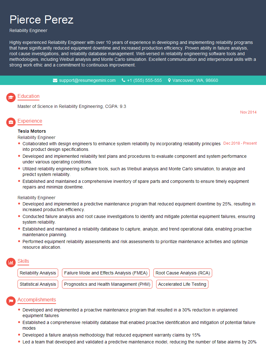
Reliability Engineer Resume Sample

Systems Engineer Resume Sample
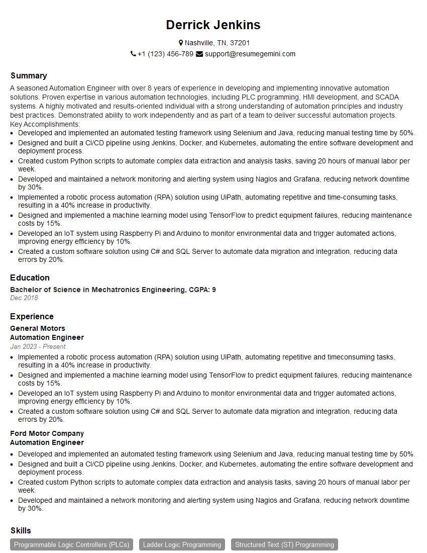
Automation Engineer Resume Sample
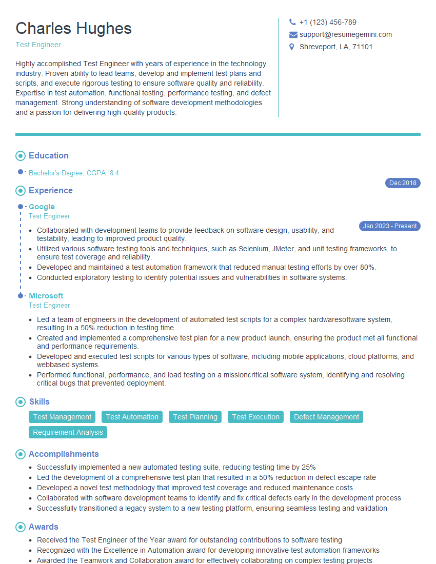
Test Engineer Resume Sample
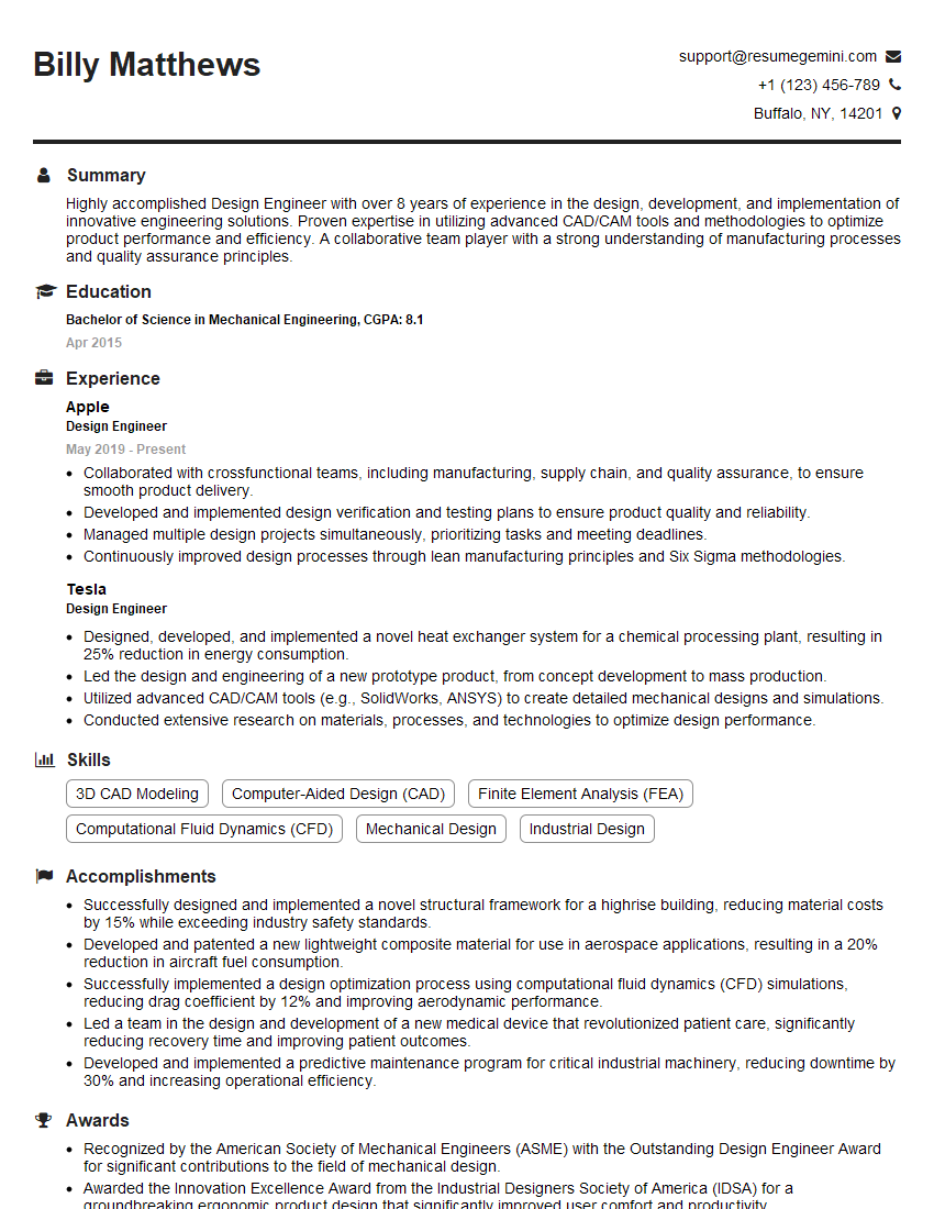
Design Engineer Resume Sample

Hardware Engineer Resume Sample

Electrical Engineer Resume Sample
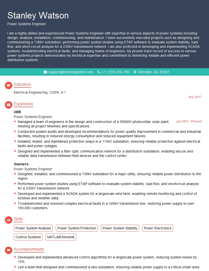
Power Systems Engineer Resume Sample
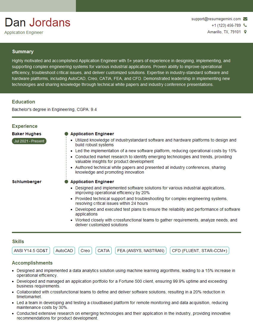
Application Engineer Resume Sample

Validation Engineer Resume Sample
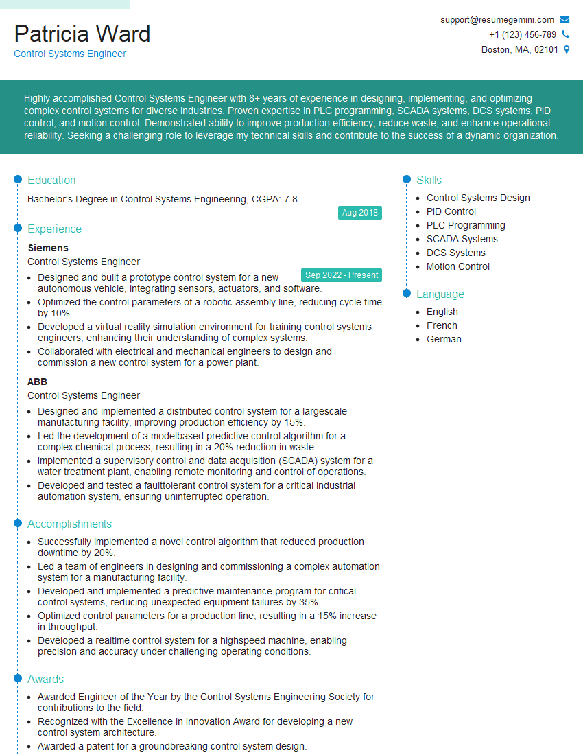
Control Systems Engineer Resume Sample
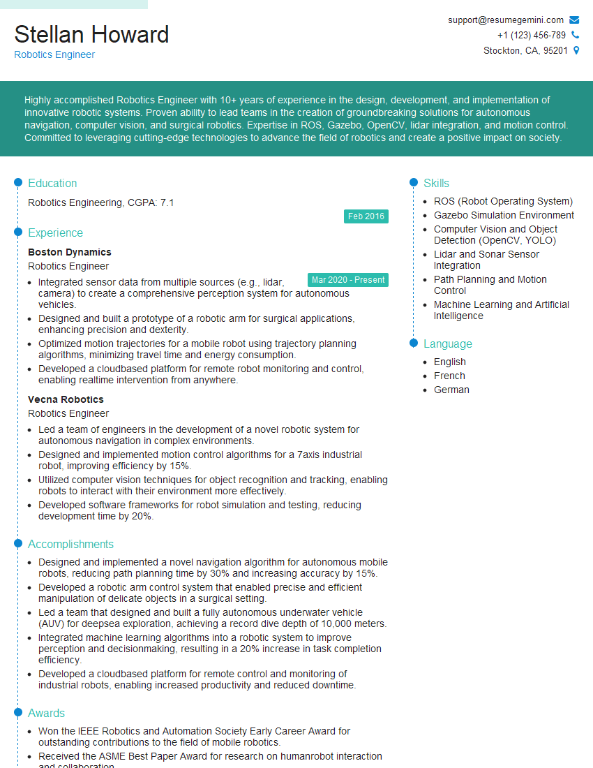
Robotics Engineer Resume Sample
Explore more articles
Users Rating of Our Blogs
Share Your Experience
We value your feedback! Please rate our content and share your thoughts (optional).
What Readers Say About Our Blog
Amazing blog
Interesting Article, I liked the depth of knowledge you’ve shared.
Helpful, thanks for sharing.